Different gadgets have been introduced to meet our requirements ranging from the basic needs to the classy needs of humans. With this development in recent years, people have grown more sophisticated day by day. Hereby we have presented a circuit sound VU meter using Arduino to display the volume of noise picked up by a microphone.
Circuit Description of Sound VU Meter using Arduino
The push-to-on switch SW1 is used to change the mode of the sound VU meter. In normal mode, the LEDs just flicker up and down with the volume of sound, while in advance mode, the LEDs register the maximum value and light the LEDs, so the sound level gradually pushes up.
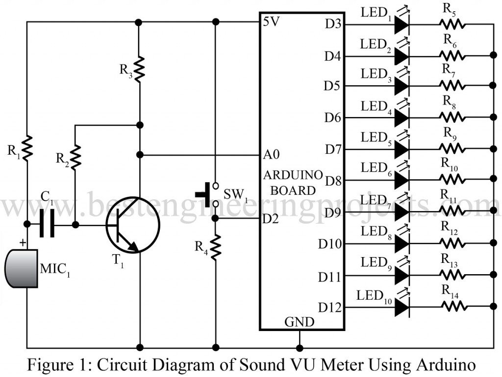
Transistor T1 boosts up the sound signal from the microphone and is fed to analog input A0 of the Arduino board as shown in the circuit diagram. Here we used a collector-feedback bias, which takes a portion of a voltage from the output and is again given to the base of the transistor.
Various other Sound VU Meter posted on bestengineeringprjects.com are:
- Arduino VU Meter
- VU Meter Circuit using ATmega32
- Sound Level Meter Circuit
- Sound Level Meter Circuit using Arduino
PARTS LIST OF SOUND VU METER USING ARDUINO
| Resistor (all ¼-watt, ± 5% Carbon) |
| R1, R3, R4 = 10 KΩ
R2 = 100 KΩ R5– R14 = 270 Ω |
| Capacitor |
| C1 = 100 nF (Ceramic Disc Capacitor) |
| Semiconductors |
| Arduino Diecimila or Uno or clone
T1 = BC548 (General Purpose NPN transistor) LED1 – LED10 = 5-mm any color LED |
| Miscellaneous |
| SW1 = Push-to-on switch
MIC1 = Electret Microphone |
Software: The sketch of the project is quite straightforward and is given below:-
|
1 2 3 4 5 6 7 8 9 10 11 12 13 14 15 16 17 18 19 20 21 22 23 24 25 26 27 28 29 30 31 32 33 |
int ledPins[] = {3, 4, 5, 6, 7, 8, 9, 10, 11, 12}; int switchPin = 2; int soundPin = 0; boolean showPeak = false; int peakValue = 0; void setup() { for (int i = 0; i < 10; i++) { pinMode(ledPins[i], OUTPUT); } pinMode(switchPin, INPUT); } void loop() { if (digitalRead(switchPin)) { showPeak = ! showPeak; peakValue = 0; delay(200); // debounce switch } int value = analogRead(soundPin); int topLED = map(value, 0, 1023, 0, 11) - 1; if (topLED > peakValue) { peakValue = topLED; } for (int i = 0; i < 10; i++) { digitalWrite(ledPins[i], (i <= topLED || (showPeak && i == peakValue))); } } |
R1 is indicated two times with different resistance values. First as 10KOhms then as 100KOhms. What to do?
Hi, Carlos, thank you for letting us know.
The value of R1 is 10K0ohm, and we have corrected it.