Atmega16 based voting machine: Well, the key word; Corruption is everywhere. I believe it is what comes together with politics. Yes, here we present an attempt to sweep a dirt away from this system. The project is concerned with development of an electronic voting machine which is built around an AVR microcontroller, which help us to create a fair election process at least. Electronic voting machines (EVMs) have been a necessity in government elections. On comparison to traditional methods, this machine provides a far more secure voting environment and reliable outcomes throughout the process. Include a compact sized machine and the job is done, their small size, low cost, portable and accuracy features add up to the mark and hence these machines are everywhere in such a short period.
Now, let’s discuss about the construction section, as stated earlier, the project is wrapped around the AVR ATmega16A microcontroller. There are switches placed in the system, and all it takes is one press to deliver the vote.
The switches are adjusted alongside the candidate’s name. When an individual press the switch, it is saved in the microcontroller and the LCD confirms the successful voting process with a meaningful message like “Thank You” to indicate the same.
Circuit and Working of ATmega16 Based Voting Machine
AVR microcontroller(IC2) lies at the center as the heart component of the circuit surrounded by another IC 7805 (IC1), a 16×2 LCD (LCD1) and few discrete components to complete the circuit.
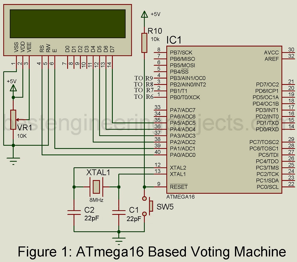
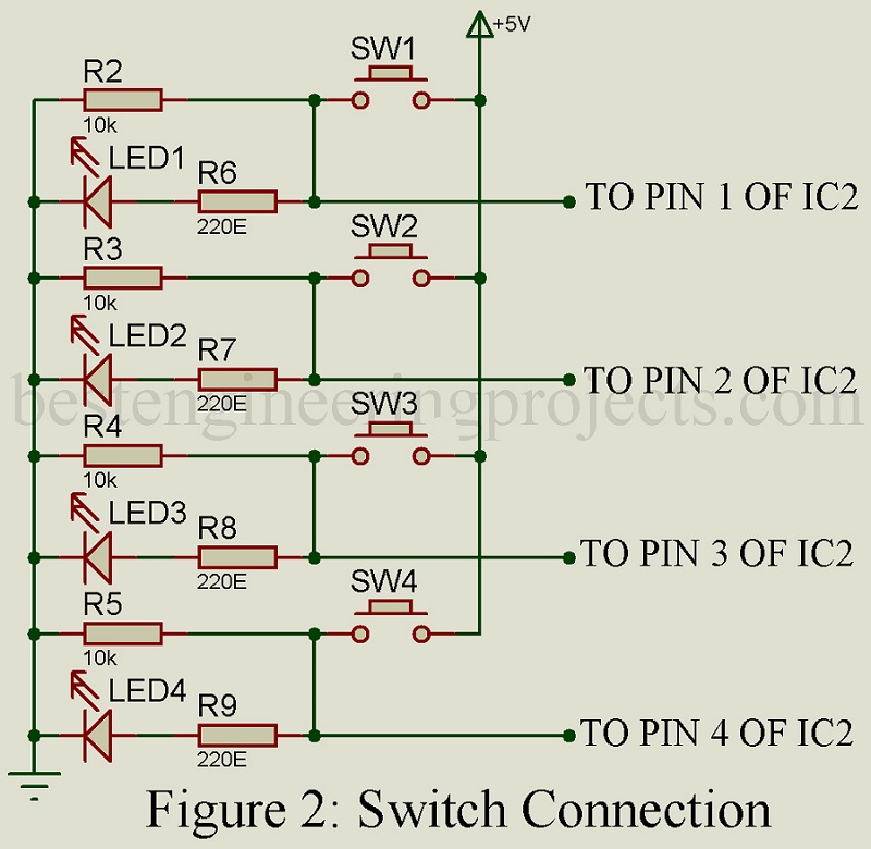
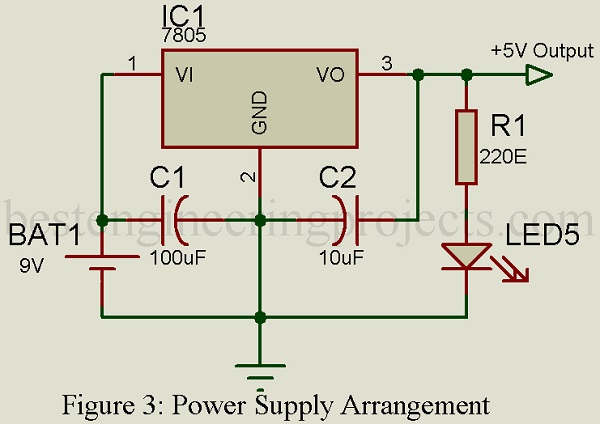
The project works on a 5V power supply and that is why we have IC1; a 7805-voltage regulator to give the power project needs from stepping a 9V DC supply to a 5V power. To avoid the ripple effects in the circuit, two capacitors; C1 and C2 are incorporated in the circuit. There are altogether 32 general purpose input/output (I/O) pins in the microcontroller. The timing pulse is provided by the 8MHz crystal oscillator. For this particular project, we have included four switches; SW1-SW4 which are respectively connected at the port B of microcontroller IC1; PB0, PB1, PB2 and PB3.
The LCD is interfaced to IC2, data pins(D4-D7) of LCD connected with Port A pins(PA2-PA5) respectively. It operates in 4-bit mode. PA0 and PA1 pins connect the control pins RS and EN of the LCD.
Normally, the LCD display is set to 5×7-pixel matrix each character pattern. For a change, you can use a 10-kilo-ohm preset and alter the contrast setting of the LCD. Take notes of the fuse bit settings of the microcontroller; low fuse bit value-E4 and high fuse bit value-D9, before loading the program onto the chip of IC2.
Software for ATmega16 Based Voting Machine
Like many projects, it uses C language and Keil software as its compiler. So as to program the microcontroller, you can make use of any software.
Assembly and testing
The assembling process is done on a PCB and after that don’t forget to check for connection faults that can cause a delay in project later on. Using a suitable programmer, burn the hex code file onto the IC2. Fix the IC2 on the soldered base and pass the power supply to the circuit through a 9V battery. As the project starts up a message “Press any key” will be displayed on the LCD.
|
Table 1 |
||
| S.N. | Switch | Operation |
| 1. | SW1 | Party 1 |
| 2. | SW2 | Party 2 |
| 3. | SW3 | Party 3 |
| 4. | SW4 | Result |
| 5. | SW5 | Reset |
There are four switches installed in the project out of which only three are used for casting votes for respective candidates from respective parties. Like switch SW1 for Party1, SW2 for party2 and SW3 for party3. The fourth switch SW4 is used to generate the collective results of the voting process.
When an individual press a switch(SW1-SW3) the connection between the respective microcontroller pin and Vcc is established and the circuit follows the designed program. The LCD flashes “Thank You” message to indicate the voting is done and corresponding LED(LED1-LED3) glows to indicate the same.
At the end, switch SW4 is used to find the winner and his/her total votes. To see if two parties have equal votes, press switch SW4 twice.
CLICK HERE TO DOWNLOAD SOFTWARE CODE
PARTS LIST OF ATmega16 BASED VOTING MACHINE
| Resistors (all ¼-watt, ± 5% Carbon) |
| R1 = 220 Ω
R2 – R5, R10 = 10 KΩ R6 – R9 = 220 Ω VR1 = 10 KΩ |
| Capacitors |
| C1 = 100 µF, 16V (Electrolytic Capacitor)
C2 = 10 µF, 16V (Electrolytic Capacitor) C3, C4 = 33pF (Ceramic Disc) |
| Semiconductors |
| IC1 = 7805
IC2 = ATmega16 LED1 – LED4 = 5mm Green Color LED LED5 = 5mm Red Color LED |
| Miscellaneous |
| BATT1. 9V Battery
XTAL1 = 8 MHz Crystal SW1 – SW5 = Push-To-On Switch |
Various other Electronics Projects based on ATmega16 Microcontroller, you may like
- GPS Module Interface with ATmega16
- Ultrasonic Water Level Meter
- Restaurant Menu Ordering System
- Wireless Temperature and Humidity Indicator for Fridge