A speech filter circuit is a broadband filter and is also called a wide bandpass filter circuit because its bandwidth is restricted to the speech frequency. It can be formed by simple cascading high pass and low pass section and is generally the choice for simplicity of design and performance through such a circuit can be realized by a number of the possible circuits. The butter-worth filter is generally used in audio systems which are characterized by a maximally flat-flat filter.
Description of Speech Filter Circuit:
A speech filter using an R-C network for filtering is illustrated in Figures 1 and 2. The working and circuit description of this circuit is almost the same. In order to describe this circuit, we shall divide this circuit into a two-part high pass filter and low pass filter. Here, we discuss only the low pass filter section because the high-pass filter is the complement of the low pass filter and is formed simply by exchanging the place of the resistor and capacitor.
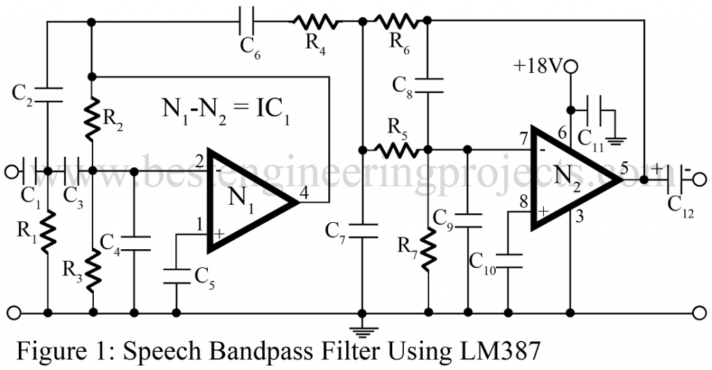
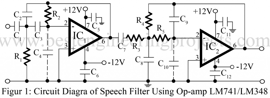
The op-amp IC is used in inverting mode so that it does not load the R-C network. The gain of the filter is determined by the op-amp, feed-back resistor, and resistor connected to earth (R3 or R7). Its gain bandwidth (GBW) and slew rate must allow it to operate well beyond the circuit frequency. Otherwise, the filter response may be practically caused by the op-amp’s frequency response.
The value of the capacitor connected to the non-inverting pin to earth (C5 or C10) must be equal to or less than 1 µF. Mylar or tantalum capacitors are recommended for better performance. The input resistor R5 strongly affects the input impedance as well as cutoff frequency so its value must be less or equal to 200 KΩ. In order to minimize the effect of bias current on the output, feed-back resistor and resistor R7 must be selected of such values so as to give
R = Rf || R7
PARTS LIST OF SPEECH FILTER CIRCUIT FOR FIGURE 1:
| Resistor (all ¼-watt, ± 5% Carbon) |
| R1 = 270 KΩR2 = 1 MΩR3 = 180 KΩR4, R6 = 330 KΩ
R5 = 150 KΩ R7 = 82 KΩ |
| Capacitors |
| C1 – C3 = 1.2 KpF (Ceramic Disc)
C4 = 0.033 µF (Ceramic Disc) C5, C10 = 0.1 µF (Ceramic Disc) C6 = 0.22 µF (Ceramic Disc) C7 = 470 pF (Ceramic Disc) C8 = 120 pF (Ceramic Disc) C9 = 0.01 µF (Ceramic Disc) |
| Semiconductors |
| IC1 (N1 – N2) = LM387 (op-amp) |
PARTS LIST OF SPEECH FILTER CIRCUIT FOR FIGURE 2:
| Resistor (all ¼-watt, ± 5% Carbon) |
| R1 = 220 KΩ
R2 = 1 MΩ R3, R4 = 330 KΩ R5 = 150 KΩ |
| Capacitors |
| C1 – C3 = 1.2 KpF (Ceramic Disc)
C4 = 0.04 µF (Ceramic Disc) C5, C6, C11, C12 = 0.1 µF (Ceramic Disc) C7 = 0.22 µF (Ceramic Disc) C8 = 470 pF (Ceramic Disc) C9 = 120 pF (Ceramic Disc) C10 = 0.02 µF (Ceramic Disc) |
| Semiconductors |
| IC1 (N1 – N2) = LM741 or LM348 |