Maximum Collector Circuit Efficiency of Class A Amplifier
Conversion Efficiency
An amplifier draws a.c. power from dc supply (collector supply VCC in CE amplifier) and converts a part of it into useful a.c. power delivered to the load impedance. The ratio of the a.c. output power to the d.c. power from the supply source in the output is called the conversion efficiency, also called collector circuit efficiency in the case of CE amplifier and is denoted by Greek letter .
Thus, ……(1)
For present analysis, we assume a resistance load. Then the average input from the dc supply is VCCIC. Out of this total dc power, a part PD is dissipated in the collector of the transistor while the rest is absorbed by the output circuit and equal (IC2R1 + IcVc) where Ic and Vc are the rms values of output current and output voltage respectively and R1 is the static load resistance. Then by the principle of conservation of energy,
…….(2)
But …..(3)
Hence, …..(4)
In case load impedance is not a pure resistance and has power factor of , then VcIc should be replaced by
.
Power PD dissipated by the active device (transistor) as given in equation (4) represents the kinetic energy of the electrons which gets converted into heat when these electrons bombard the collector. With zero signal a.c. output power VcIc become zero and as per equation (4), PD is maximum and equal VcIc. Thus, the device is cooler when delivering power to the load impedance than under zero signal condition.
Under actual operating conditions with distortion present,
Signal power delivered to load …..(5)
D.C. power supplied to the output circuit = …..(6)
Hence conversion efficiency is,
…….(7)
In case the distortion terms are negligible small, then
……(8)
Overall Efficiency
It is the ratio of a.c. output power delivered to the load to the dc power from the output (collector) circuit source plus the dc power from the base circuit. Thus, overall efficiency is smaller than the collector circuit efficiency.
Maximum Collector Circuit Efficiency of Class A Amplifier
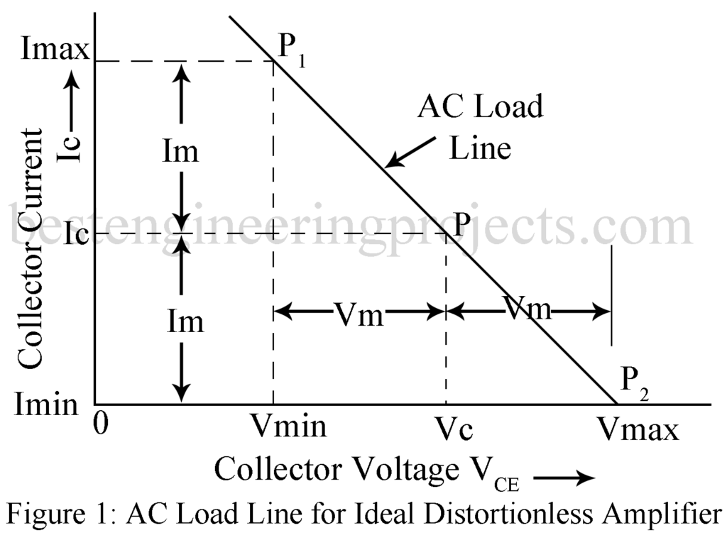
For assessing the maximum collector circuit efficiency, we use idealized collector characteristic curves i.e. curves which are assumed linear, parallel and equi-spaced for equal increments of the excitation (base current) in the region of the load line. Figure 1 gives the a.c. load line extending from P1 to P2 with P as the zero-signal operating point.
Length P1P = P2p.
We further assume that the excitation is such that the minimum collector current is zero i.e. P2 lies on the voltage axis.
In figure 1, Im and Vm give the peak values of time varying collector current and collector voltage respectively. The condition depicted in figure 1 may then be used for analysis of either the series fed load or the transformer fed load. However, the difference in the two cases is that the supply voltage VCC equals quiescent collector voltage VC in the case of transformer coupled load neglecting the static d.c. drop.
Under such ideal condition,
…….(9)
And …….(10)
Then from equation (8)
……(11)
We here consider the following two different cases:
- Series fed amplifier and
- Transformer coupled amplifier.
Series-fed Class A Amplifier
For Series fed amplifier VCC = Vmax. Hence Equation (11) yield,
……..(12)
From Equation (12) we find that conversion efficiency for series fed class A amplifier approaches its maximum value of 25% when Vmin approaches zero. In actual practice, however, in considerably smaller than this value of 25%, typically value being only 15%.
Transformer Coupled Class A Amplifier
For this amplifier, ………(13)
Hence from equation (11),
……(14)
From equation (14) we find that the maximum theoretical conversion efficiency of a transformer coupled class A amplifier is 50% i.e. twice the maximum theoretical conversion efficiency of series fed class A Amplifier. In a transistor amplifier, Vmin lies close to the saturation region. Hence Vmin << Vmax. Hence, in practice, the collector circuit efficiency of a transformer coupled class A transistor amplifier is quite close to 50%.
An accurate determination of numerical value of the collector circuit efficiency may be done on using Equation (7). On the other hand, Equations (12) and equation (14) gives only approximate values and the error involved may be quite large since the idealized conditions are never achieved in practice.
