Stereo Amplifier Circuit Diagram we are going to design here is basically the combination of two mono audio amplifier. Portable and good audio amplifier is still a major concern to many electronic hobbyists and professional. People are still searching for good portable and battery-operated stereo amplifier. So, here in this article you will learn about designing of stereo amplifier using two audio amplifier IC. This stereo amplifier works with low voltage battery (4.5V, 6V) or even with a USB interface (+5V). In order to achieve above specification, we most design system having low quiescent current.
Stereo amplifier Circuit Diagram is different then traditional mono amplifier in two ways.
- It takes two inputs i.e. left and right and produce two output i.e. left and right.
- It can also amplify mono sound and produce the output in two different speakers i.e. left and right.
In the website bestengineeringprojects.com we had already posted various mono and stereo amplifier circuit projects of various power range. You may also like:
- 10 Watt Audio Amplifier Circuit with Volume Control
- Audio Distribution Amplifier Circuit using LM324
- 20 Watt Audio Amplifier using TDA2003
- Low Power Audio Amplifier Using LM386
- 8W + 8W Stereo Amplifier Circuit with Graphic Equalisers
Let’s see the circuit diagram of stereo amplifier
The circuit of stereo amplifier is built around TDA7052 audio amplifier IC. There are few special features which lead us to design this stereo amplifier circuit using this particular IC.
- Output power of 1.5W which is enough power for a room with several people.
- Lowe power consumption thus ideal for battery operation (can be operated using USB interface).
- In built DC volume control and can be controlled using variable resistor.
- No click sounds in speaker even at the time of ON and OFF.
- Various protection like thermal, short-circuit and EDS Protection.
Description of Stereo Amplifier Circuit Diagram
For proper description we are dividing the circuit into two distinct section i.e. power supply section and audio amplifier section.
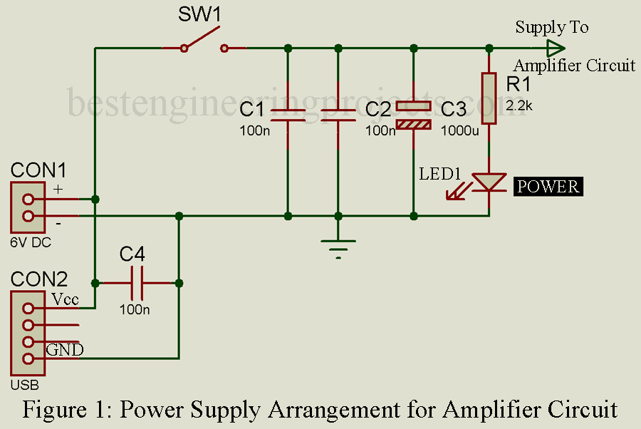
Power supply Section | Stereo Amplifier Circuit Diagram
You can power the circuit in two way i.e. either through 6V DC power supply or you can also use USB power supply. The output of this power supply is further filtered using three different capacitors in order to filter out the AC component if any available. We need to filter out AC components because this might produce hum sound in speaker. LED1 is used to indicate the presence of power supply.
Audio Amplifier Circuit | Stereo Amplifier Circuit Diagram
This stereo amplifier is basically the combination of two mono audio amplifier. So, here I am describing the operation of only one amplifier because another amplifier is just a replica.
Stereo input is given to analog IN jack which is connected to +IN pin of IC1 and IC2 (TDA7052) through RC Network as shown in circuit diagram. Variable resistor is used to control the volume where capacitor C5 and C6 is used to block the DC components if available in audio signal.
Resistor R3 and R6 is used here in order to reduce input resistance as a result output noise is reduced and produce better output.
Positive and negative output is obtained at pin 5 and 8 respectively. Speaker is connected to this output pins. Two LEDs is connected to each output through current limiting resistor in order to indicate the audio output. LED2 and LED3 is used to indicate the audio output of left channel where LED4 and LED5 is used to indicate the audio output of right channel.
Operation of Stereo Amplifier Circuit Diagram is described in different mode.
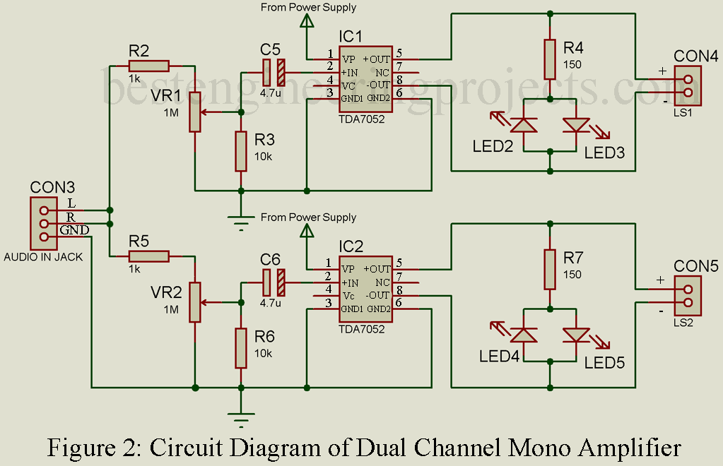
Mode 1: In this mode the amplifier is works as dual channel mono amplifier shown in figure 2. Single input (Mono) is given to audio IN and it produce output in both the speaker.
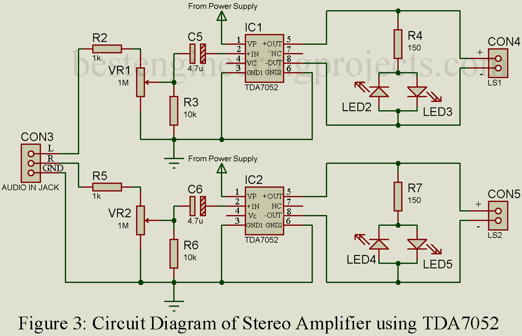
Mode 2: In this mode the amplifier is worked as stereo amplifier which accept stereo input and produce stereo output shown in figure 3.
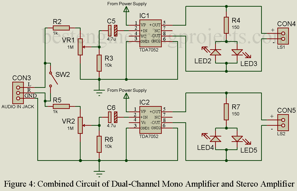
Both the circuit can be combined by adding one extra SPST switch which can be used for both mono dual channel audio amplifier and stereo amplifier as shown in figure 4. When the switch SW2 is closed this circuit is used as mono amplifier, when switch SW2 is open it works as stereo amplifier.
PARTS LIST OF STEREO AMPLIFIER CIRCUIT DIAGRAM
| Resistor (all ¼-watt, ± 5% Carbon Unless Stated Otherwise) |
| R1 = 2.2 KΩ
R2, R5 = 1 KΩ R3, R6 = 10 KΩ R4, R7 = 150 Ω VR1, VR2 = 1 MΩ |
| Capacitors |
| C1, C2, C4 = 100nF
C3 = 1000 µF, 25V C5, C6 = 4.7 µF, 25V |
| Semiconductors |
| IC1, IC2 = TDA7052
LED1 – LED5 = 5mm any color LED |
| Miscellaneous |
| CON1, CON4, CON5 = 2 PIN Connector (For power supply and speaker)
CON2 = 4 PIN Connector (USB Female) CON3 = 3 PIN Connector (Audio Input Jack) LS1, LS2 = 8-Ohm 1-Watt Loud Speaker SW1, SW2 = SPST ON/OFF Switch |