The circuit ‘Battery Level Indicator’ is simple, cheap, and compact. It can be used in emergency lights and other power supply circuits. We are using this simple circuit ‘battery level indicator’ for over a year and has found it works well in emergency light as well as battery charger circuit. We already indicate various battery voltage states using IC, this time we come with a little different concept and circuit for battery indication.
Other battery level circuits posted in bestengineeringprojects.com
- Battery Status indicator Circuit
- 10 Level Battery Charge Indicator Circuit
- Battery Voltage State Indicator using 741 IC
Circuit Description of Battery Level Indicator
The circuit is shown in figure 1 and build around two general-purpose NPN transistors, two LEDs, and a few resistive components (resistor and variable resistor). Battery’s levels, normal or low, are indicated by the green or red LED respectively. One can set the circuit for monitoring the level of the battery within 3 to 10 volts with the help of a 10K preset.
Normally, transistor T1 is ‘ON’ due to the voltage divider biasing. Green LED is ‘ON’ as the collector of T1 is almost at ‘ground’.
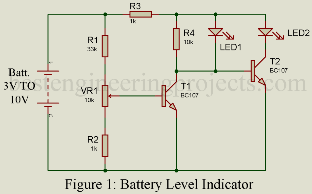
When the voltage drops below the preset voltage, T1 switches off as the voltage is not sufficient to bias it to the ‘ON’ state. But the voltage at the bias of T2 is sufficient to switch on T2 to condition. Thus, red glows-indicating the under-voltage state of the battery.
The entire gadget costs $0.35. this circuit can be comfortably placed inside a cabinet, with the LEDs fitted on the cover.
PARTS LIST OF BATTERY INDICATOR CIRCUIT
Resistors (all ¼-watt, ± 5% Carbon else Specified)
R1 = 33 KΩ
R2, R3 = 1 KΩ
R4 = 10 KΩ
VR1 = 10 KΩ (Preset.)
Semiconductors
T1, T2 = BC107 (Low Power General Purpose Bipolar Transistor)
LED1 = Green LED 5mm LED
LED2 = RED LED 5mm Led
Miscellaneous
BAT1. = 3 Volt to 10 Volt Battery Under Test