Today, in this article, you will learn how to make Three Phase AC Voltage Measurements using Arduino. At first, we will show you how to measure single-phase AC voltage and then measure three-phase AC voltage.
Features of Three Phase AC Voltage Measurement using Arduino:
- Can measure AC voltage of any amplitude.
- Show individual phase voltage.
- LED indication for individual phase voltage.
- For the protection of the control board (Arduino Board), a variable resistor is used i.e. output voltage must not be more than 4.5V even when Zener diode burnout.
Working Principle:
High AC input voltage is first converted to lower AC voltage with the help of a transformer and then rectifier using a full-wave bridge rectifier. The output of the rectifier is given to the voltage divider network which lowers the rectified output DC voltage and further filters and passes to the zener diode. The output is given to Arduino input analog input pin A0.
Circuit Description of Three Phase AC Voltage Measurement using Arduino:
The circuit is very simple and easy to understand and is designed around the transformer, bridge rectifier, zener diode, Arduino uno, LCD, and a few other components like resistor and capacitor, etc.
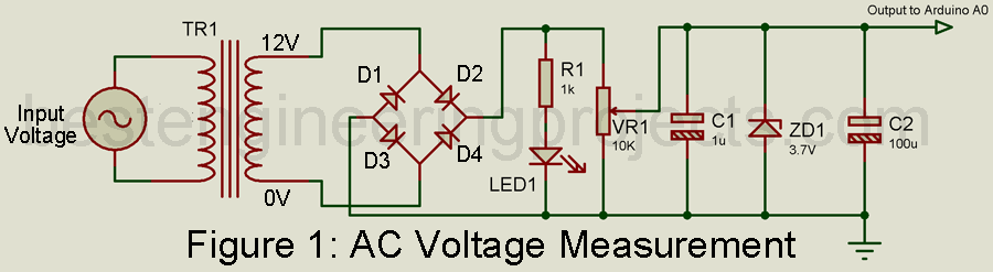
The input AC voltage to be measured is given to the primary side of transformer X1, which lowers the high input voltage (say 220V AC) to low AC voltage (say 12V AC) in this case. Arduino cannot measure the negative half cycle as input thus we need to either clip or have to change the negative half cycle to the positive half cycle. To do the show, we are using a bridge rectifier. Check out the article on full-wave bridge rectifiers to know more about rectification.
The stepdown AC voltage (12V AC) is rectified using four diodes (1N4001). The rectified output is fed to a voltage divider network designed using variable resistor VR1. Two fixed terminals of the variable resistor are connected to the positive and negative terminal of rectified output as shown in the circuit diagram. Output is taken from the variable wiper of variable resistor VR1. The output is now filtered using capacitors C1 and C2. A zener diode is used here to protect the zener diode which breakdown when the input voltage exceeds 3.7V. This output voltage is now given to Arduino uno analog pin A0.
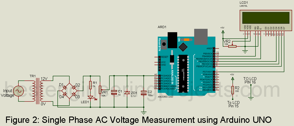
Arduino measure this voltage and displayed it over LCD. LCD is connected to Arduino in higher-order data bit i.e. only higher-order data pin (D4 to D7) is used for communication between Arduino and LCD. Data pins D4 to D7 are connected to Arduino D10 to D7 respectively as shown in the circuit diagram. Where EN and RS pin is connected to Arduino D11 and D12 respectively. Vss, RW and LED- pin of LCD is connected to GND where VDD pin is connected to +5V. VEE pin is responsible for contrast adjustment and the supply voltage must be between VDD and VSS thus wiper pin of VR2 is connected to this pin. LED+ pin of LCD is connected to +5V through a current limiting resistor as shown in the circuit diagram.
Check out the tutorial video on How to Interface Arduino and LCD
Calibration Software Code
|
1 2 3 4 5 6 7 8 9 10 11 12 13 14 15 |
int ACInput = A0; //Pin assigning for R Phase //Setup function Start void setup() { pinMode(ACInput, INPUT); Serial.begin(9600); } //Loop Function Start Here void loop() { int vrout = analogRead(ACInput); //Read the division at analog pin A0 (0 to 1023) Serial.println(vrout); // Display the R-Phase voltage on serial monitor delay(500); } |
How to Calibration:
Procedure for calibration
- Measure AC mains voltage using a multimeter (in the context of Nepal it is 230V ideally but practically it shows 227V AC).
- Adjust the variable resistor so that the output voltage from the Zener diode is constant and lower than 3.7V (Say 2.66V DC).
- Upload the calibrating software to your Arduino and open Serial Monitor.
- It displays some value (say 545). Save the value because we need it for further calculation. Adjust the variable resistor to achieve this value (545)
- Now, calculate the multiplier.
For 5V DC Arduino show a 1023 value, similarly, by using the unitary method we can calculate voltage for 1 division it shows
1023 = 5V;
1 = 5/1023 V
Thus for, 545 division voltage = (5/1023)*545 = 2.66V.
When the mains voltage is 227V AC Arduino shows 2.66V, by using the unitary method
Multiplier = 227V / 2,66V = 85.30
Therefore, Multiplier = 85.30.
Software Code for Single Phase AC Voltage measurement:
|
1 2 3 4 5 6 7 8 9 10 11 12 13 14 15 16 17 18 19 20 21 22 23 24 25 |
#include <LiquidCrystal.h> LiquidCrystal lcd(12, 11, 10, 9, 8, 7); //(RS,EN,D4,D5,D6,D7) int Volt = A0; //Pin assigning for AC Voltage //Setup function Start void setup() { pinMode(Volt, INPUT); lcd.begin(16,2); Serial.begin(9600); } //Loop Function Start Here void loop() { lcd.clear(); int AcVolt = analogRead(Volt); //Read the division at analog pin A0 (0 to 1023) int AcVoltOut = (AcVolt * (5.0 / 1023))*93.67; // Convert the AC divison into volt Serial.println(AcVoltOut); // Display the AC voltage on serial monitor lcd.setCursor(0,0); lcd.print("AC Voltage"); lcd.setCursor(0,1); lcd.print(AcVoltOut); // Display the AC voltage on LCD delay(500); } |
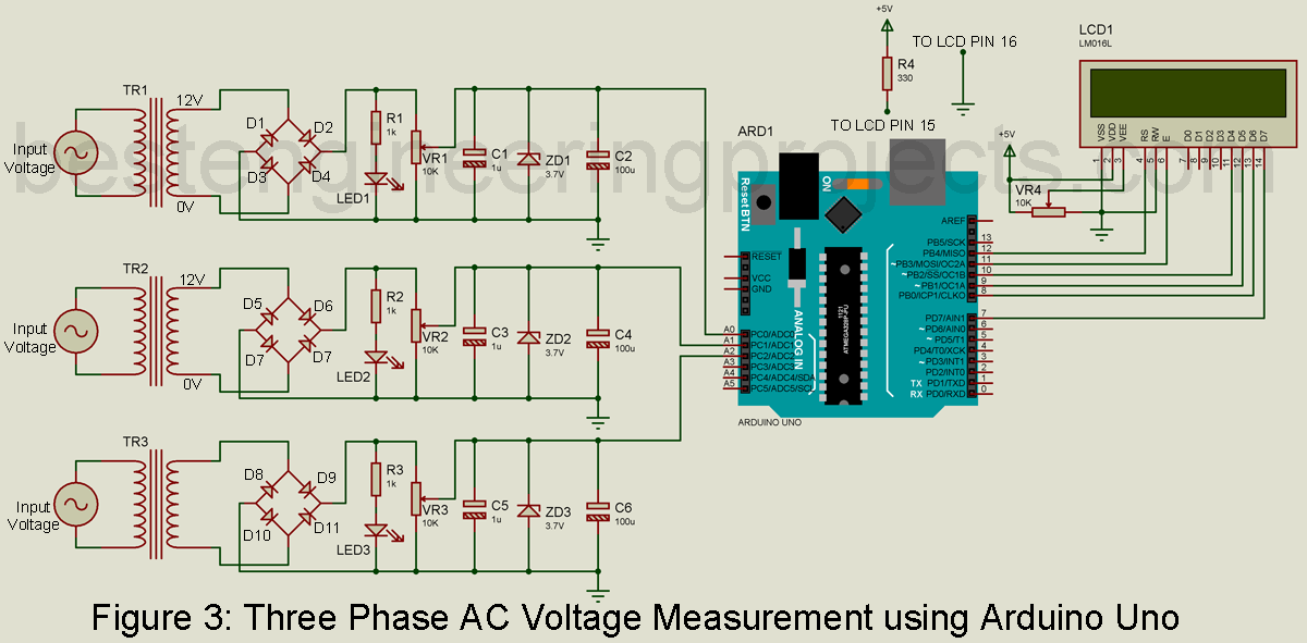
Circuit for Three-Phase Voltage Measurement
The circuit for three-phase AC voltage is the same as that of single-phase with two extra single-phase voltage measurements.
Software Code for Three Phase AC Voltage Measurement using Arduino
|
1 2 3 4 5 6 7 8 9 10 11 12 13 14 15 16 17 18 19 20 21 22 23 24 25 26 27 28 29 30 31 32 33 34 35 36 37 38 39 |
#include <LiquidCrystal.h> LiquidCrystal lcd(12, 11, 10, 9, 8, 7); //(RS,EN,D4,D5,D6,D7) int RPhase = A0; //Pin assigning for R Phase int YPhase = A1; //Pin assigning for Y Phase int BPhase = A2; //Pin assigning for B Phase //Setup function Start void setup() { pinMode(RPhase, INPUT); pinMode(YPhase, INPUT); pinMode(BPhase, INPUT); lcd.begin(16,2); Serial.begin(9600); } //Loop Function Start Here void loop() { lcd.clear(); int vrout = analogRead(RPhase); //Read the division at analog pin A0 (0 to 1023) int vyout = analogRead(YPhase); //Read the division at analog pin A1 (0 to 1023) int vbout = analogRead(BPhase); //Read the division at analog pin A2 (0 to 1023) int RVolt = (vrout * (5.0 / 1023))*93.67; // Convert the R-Phase divison into volt int YVolt = (vyout * (5.0 / 1023))*93.67; // Convert the Y-Phase divison into volt int BVolt = (vyout * (5.0 / 1023))*93.67; // Convert the B-Phase divison into volt Serial.println(RVolt); // Display the R-Phase voltage on serial monitor Serial.println(YVolt);// Display the Y-Phase voltage on serial monitor Serial.println(BVolt); // Display the B-Phase voltage on serial monitor lcd.setCursor(0,0); lcd.print("R Y B "); lcd.setCursor(0,1); lcd.print(RVolt); // Display the R-Phase voltage on LCD lcd.setCursor(4,1); lcd.print(YVolt); // Display the Y-Phase voltage on LCD lcd.setCursor(8,1); lcd.print(BVolt); // Display the B-Phase voltage on LCD delay(500); } } |
Check out other top popular Articles :
Clock Signal Generator Circuit
I tried the simulation, it didn’t work, I wonder what did I do wrong