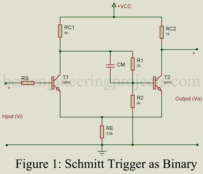
Fig 1 gives the schematic circuit of Schmitt trigger. It forms an important bistable multivibrator and differs from the basic Eccles-Jordon bistable multivibrator of Fig 1 in that (i) from output point C2 of T2 to the input of transistor T1 is missing and (ii) the feedback through resistor RE. Using transistors, the circuit is basically an emitter coupled binary. It is called Schmitt trigger after the name of the inventor of the vacuum tube Version.
In this circuit, also there are two stable states. This results because of positive feedback with loop gain greater than unity.
Operation of Schmitt Trigger
Let us assume initially that the loop gain is kept less than unity (one) by using small value of resistor RC1. Then there is no regeneration. Hence the circuit does not operate as a binary (flip-flop), but may be used as an amplifier with input voltage vi applied at B1 as shown in Fig 1 and let v0 be the output voltage at C2.
If transistor T2 is conducting, there result a voltage drop across RE, which raises the potential of emitter of T1. Hence with small input vi, T1 is cutoff. The output at C2 is then given by,
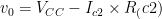 ……(1)
……(1)
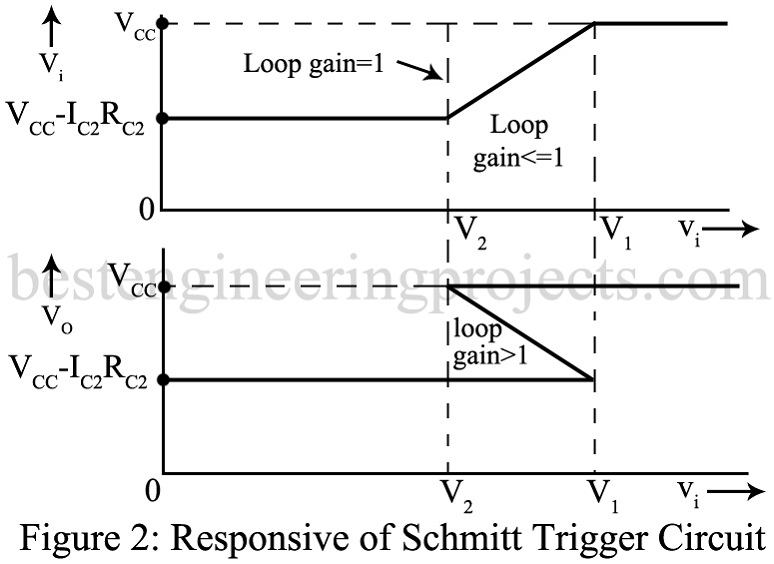
As vi is progressively increased, circuit will respond only when T1 reaches its cutin value say V2. Then T1 conducts. With T1 conducting, circuit amplifies and since  is positive, output vo rises in response to the rise in vi. As vi continues to rise, voltage at B2 continues to fall and the voltage at E2 continues to rise. Ultimately a value of vi equal to V1 is reached when T2 is turned OFF. Voltage vo equals Vcc and the output again becomes insensitive to changes in vi. Solid curve in upper diagram of Fig 2 shows the variation of vo with vi for loop gain less than one.
Next let the loop gain be increased by increasing Rc1. This causes negligible change in the value of cutin voltage V1. However, in the region of input voltage vi where amplification occurs, voltage gain , increases and hence the slope of the curve increases. This slope continues to increase with the increase of loop gain until the loop gain becomes 1 for which value the circuit becomes regenerative and the slope becomes infinite.
The curve is then vertical as shown by the dotted line in the upper diagram of Fig 2. Finally, with loop gain greater than unity, the slope of the response curve reverses its sign i.e., vo increases with decrease in vi as shown in the lower diagram in Fig 2. The curve assumes the shape of letter S.
Hysteresis of Schmitt Trigger
With loop gain more than 1, as vi rises from zero volt, vo remains at the lower level (VCC-Ic2.Rc2) until vi reaches V1. When vi exceeds V1, a line drawn vertically cuts the response curve only at the upper level VCC. Hence with vi > V1, the circuit makes an abrupt change to this higher level VCC. Next let vi be initially in excess of V1 and let it be gradually reduced. Then the output continues to remain at its upper level VCC until vi, reaches a value V2 shown in Fig 2. For still lower value of vi, the output makes an abrupt transition to the lower level. The circuit thus exhibits hysteresis i.e. to cause a change in direction, we must first go beyond the voltage at which the reverse saturation takes place.
Application of Schmitt Trigger:
Schmitt trigger and conventional bistable multivibrator (Eccles-Jordon circuit) may be used for the same applications. However, Eccles Jordon circuit because of its symmetry, is preferred in applications where the circuit is required to be triggered back and forth between stable states. In schmitt trigger, the base of transistor T1 is not involved in the regenerative switching. Hence when the circuit switches between two stable states, the voltage of the basic terminal does not change. Hence schmitt trigger circuit is preferred wherever this free base terminal is needed. Further the resistance Rc2 in the output circuit of T2 is not required for the operation of binary. Hence this resistance may be suitably selected to achieve any desired output voltage amplitude. Further capacitive loading of the output terminal C2 does not slow down the regenerative action.
Important applications of Schmitt trigger circuit are as below:
- As an amplitude comparator
- As a squaring circuit
- As a flip-flop circuit