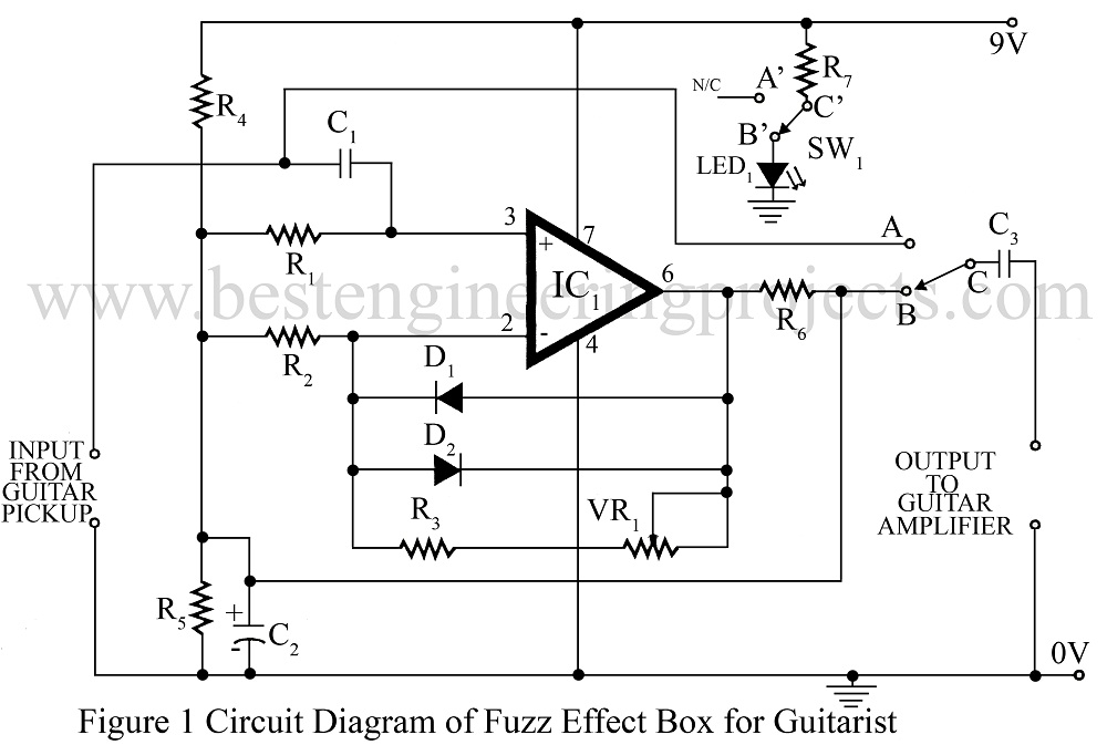
The ‘fuzz’ sound is derived by clipping the input waveform, thereby enriching the signal with odd harmonic which provide the hash sound. This circuit “Fuzz Effect Box for Guitarists” is a basic project produces a fuzz which gradually decays into a ‘clean signal’.
Circuit Description of Fuzz Effect Box for Guitarists
The circuit uses the standard op-amp 741 in non-inverting configuration. The gain of this amplifier is controlled by the feedback network comprising VR1, R2 and R3.

Input signal from the guitar passes to the op-amp through DC blocking capacitors C1. Resistor R1 sets the input impedance at 100 K, which suits most guitars. Resulting signals from the op-amp are reduced in amplitude by the potential divider action of R6 and R7 giving an attenuation factor of approximately four. Thus the maximum output signal via capacitor C3 available for inputting to an amplifier is about 150mV. This level is maintained during the period of clipping (fuzz) and then decays naturally to zero.
A foot switch may be used to bypass the signal whenever required. The whole circuit can be assembled on a general-purpose PCB. A red LED can be used to indicate that the “Fuzz Effect” is ‘ON’ by coupling it to the bypass switch suitably.
This unit Fuzz effect box for Guitarists is power by 8V PP3 battery.
Other Guitar Related Electronic Project posted in bestengineeringprojects.com
- Electric guitar preamp circuit
- Tone Control for Guitar Amplifier Using 741
- Guitar Amplifier | Convert Hawain Guitar to an Electric Guitar
PARTS LIST OF FUZZ EFFECT BOX FOR GUITARISTS
|
Resistor (all ¼-watt, ± 5% Carbon) |
|
R1 = 100 KΩ R2 = 1.2 KΩ R3 – R5 = 10 KΩ R6 = 3.3 KΩ R7 = 1.8 KΩ VR1 = 100 KΩ LIN. |
|
Capacitors |
|
C1, C3 = 0.1 µF (Ceramic Disc) C2 = 10 µF, 16V (Electrolytic Capacitor) |
|
Semiconductors |
|
IC1 = LM741 (General Purpose Operational Amplifier IC) D1, D2 = 1N4148 (silicon switching signal diode) LED1 = RED LED |
|
Miscellaneous |
|
Switch |
o/p via R6 to C2???