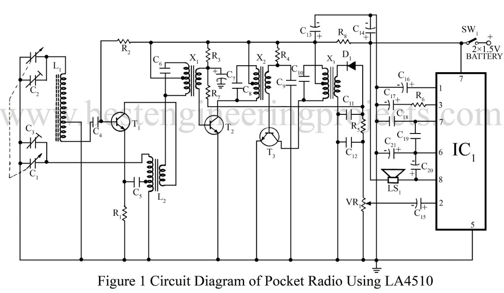
Here is a circuit for a pocket radio using one IC LA4510 and three transistors. This circuit differs from ordinary circuits at the audio stage only. Here a small 9-pin IC LA4510 is used. It replaces three transistors, a driver transformer, and many other passive components. The amplifier circuit needs only one resistor! At zero signal level, this circuit draws 8-10 mA current only. With a 3-volt supply, this circuit can give 200 mW output power.
For making this radio you may buy an ordinary pocket radio PCB and assemble IF and RF sections. LA4510 amp circuit may be assembled on a small separate Veroboard which may be fixed on the PCB using adhesive. Otherwise, you may make a new single PCB for this circuit. The 1.5-volt pen torch cells can be used to power the circuit.
Parts List of Pocket Radio Using LA4510
|
Resistor (all ¼-watt, ± 5% Carbon) |
|
R1 = 680 Ω R2 = 220 KΩ R3 = 68 KΩ R4 = 100 KΩ R5 = 560 Ω R6 = 82 Ω R7 = 33 KΩ R8 = 47 Ω VR1= 10 KΩ LOG. |
|
Capacitors |
|
C1 = 2J GANG C2, C3 = TRIMMER 39 pF C4, C5, C11, C12 = 0.01 µF C6, C8, C10 = 2700 pF C7 = 2.2 µF/10V C9 = 0.04 µF C13, C14 = 220 µF/16V C15 = 1 µF/10V C16, C21 = 47 µF/10V C17 = 22 µF/10V C18 = 0.001 µF C19 = 0.0015 µF C20 = 470 µF/10V |
|
Semiconductors |
|
IC1 = LA5410 T1 = BF194B T2 = BF195C T3 = BF195D D1 = 1N34 or OA79 |
|
Miscellaneous |
|
X1 = YELLOW IFT MIXTURE X2 = GREEN IFT INTERSTAGE X3 = WHITE IFT DETECTOR L1 = 2*MW ANTENNA COIL OVER FERRITE ROD L2 = (RED) MW OSCILLATOR COIL (IFT TYPE) LS1 = 8Ω SW1 = On/Off Switch |

what about 1895 BEL 5AA