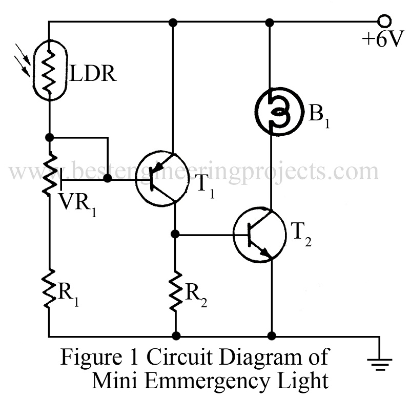
There are various type of emergency light circuits. Every circuit has its own importance and utility. But size, cost and efficiency of the circuit are some of the main feature of interest. A very simple circuit of mini emergency light is given here.
In normal daylight or electric light, the LDR offer very low resistance. So the positive voltage is applied to the base of transistor T1, making it reverse biased. Therefore, T1 does not conduct in presence of light. As transistor T2 also is reverse biased it does not conduct either. So the bulb does not glow.
In darkness, to make the bulb glow at a desired intensity of light, the LDR offers high resistance due to which a negative voltage forward bias T1. Hence T1 conducts and voltage drop across resistor R2 is applied to base of T2, causing it to conduct. In this way the bulb glows.
Preset VR1 can be adjusted to make the bulb glow at a desired intensity of light.
In presence of light, the circuit is off but draws about 125 µA from 6V supply. The total consumption of circuit depends on the bulb’s rating. If a bulb of 6V, 120mA rating is used then the circuit consumes about 300 mA current.
PARTS LIST OF MINI EMERGENCY LIGHT CIRCUIT
|
Resistor (all ¼-watt, ± 5% Carbon) |
|
R1 = 22 KΩ R2 = 220 Ω VR1 = 22 KΩ |
|
Semiconductors |
|
T1 = BC178 T2 = PT4 |
|
Miscellaneous |
|
B1 = 6V, 120 mA LDR |
