In this article, we will analyze different types of JK Flip Flip IC like dual type and Gated Master Slave JK Flip Flop, its key parameters, applications, and comments.
Description of J-K Flip Flop
The J-K flip flop and the type D flip flop described in the previous pages are the most popular and widely used types of Flip-Flips. The main difference between them is the J-K terminals replace the D-input.
As illustrated in the logic diagram of figure 1, the J-K Flip-Flip requires more logic elements but also can perform different functions. The detailed functions available are summarized in the truth table of Figure 2. Note that where there were two possible data inputs in the type D Flip-Flop, there are four possible data inputs in the J-K type because either or both of these terminals can assume the 0 or the 1 state. In the truth table of the J-K Flip-Flop, the change from the present condition of Q to the next condition of the outputs is indicated because the change rather than the static operation is the key function of the J-K Flip-Flop.

Key Parameters of JK Flip-Flip
- Quiescent current: The current drawn by the IC when no operations take place. 2.0 nA at 5V is typical for low-power CMOS.
- Toggle Rate: The maximum frequency at which the Flip-Flop changes state. 3 MHz is typical for low-power CMOS and 45 MHz is typical for low-power TTL ICs.
- Propagation delay, clock to output: The time delay from the clock pulse transition to a change in the output. 175 ns is typical for low-power CMOS and 11ns is typical for low-power TTL ICs.
- Propagation delay, set to output: The time from the application of the set pulse until a change occurs at the output. 175ns is typical for low-power CMOS and 16 ns is typical for low-power TTL ICs.
- Propagation delay, reset to output: The time required from the application of the reset signal until a change occurs at the output. 350 ns is typical for low-power CMOS and 16ns is typical for low-power TTL ICs.
- Clock pulse width: 165ns is typical for low-power CMOS and 12ns is typical for low-power TTL ICs.
Table 1: Truth Table of Dual JK Flip-Flop
Applications
J-K Flip-Flop is found in all digital equipment for control, register, or toggle functions.
Representative Part Number: Texas Instruments SN7476
Comments
Although a dual J-K Flip-Flip IC is described here, the number of J-K Flip-Flops that are available in a single IC depends only on the pin connections available. When common clock, set, or reset controls are used, more than two J-K Flip-Flops can be made available on a 16-pin standard IC.
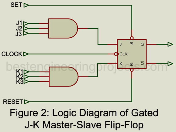
Gated J-K Master-Slave Flip-Flip
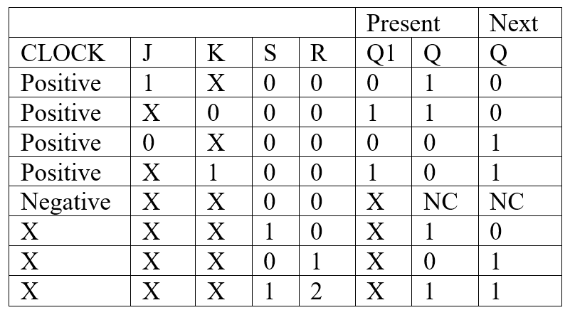
This IC illustrates the many functions that a single Flip Flop can perform. As illustrated in the function block of figure 1, the J-K Flip Flop has a 3-input AND gate connected to the J and to the K terminal. The use of the multiple J and K inputs controls the transfer of information into the master section during clock operation at the positive edge of the clock pulse. The truth tables in figure 2 illustrate both synchronous and asynchronous operations of this IC and provide some insight into the particular functions that it can perform.
Key Parameters of Gated JK Master-Slave Flip-Flop
- Maximum power dissipation: 500 mW is typical for high voltage CMOS devices.
- Quiescent current: The current is drawn when the IC is not operating. 0.02 uA is typical for high-voltage CMOS devices.
- Toggle rate: The highest frequency at which the Flip Flop can change state. 7 MHz is typical for high-voltage CMOS at 5V.
- Propagation Delay, set or reset to output: 150 ns is typical for high voltage CMOS.
- Clock pulse width: 70 is typical for high voltage CMOS ICs.
Table 2: Truth Table of Synchronous Operation of jk Flip Flop
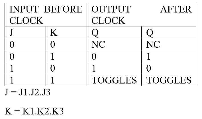
Table 3: Truth Table of Asynchronous Operation of JK Flip Flop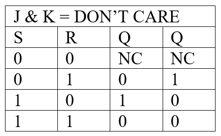
Applications
This type of Flip Flop is particularly useful in registers, counters, and control circuits where multiple data inputs must be combined.
Representative Part Number: Texas Instruments SN7472
Comments
The IC described is merely an example of the combinations of Flip Flop and gate arrangements that are available as standard ICs.