Solder Fumes Extractor Circuit: Soldering in electronics is analogous to fixing a component using glue. It is a general phenomenon in the field of electronics that involves fixing electronic components into a special board called PCB with the help of instruments like soldering iron and electrical solder commonly called ‘Solder wire’.
While soldering we all face the problem of toxic fumes. These fumes are of lead solder wire and flux. Combinedly, these fumes are highly toxic if an excess amount is inhaled. To solve this problem, here we designed a simple circuit called a solder fume extractor using an op-amp IC which removes fumes from the soldering area. The circuit posted here is of the automatic type which runs the exhaust fan during soldering and stops the exhaust fan when the soldering iron is kept on the soldering stand.
Circuit Description of Solder Fumes Extractor Circuit
The Circuit of the solder fume extractor shown in figure 1, is designed using op-amp CA3130, two NPN transistors, and a few other passive components. For fumes removal, we used a small 12V DC exhaust fan.
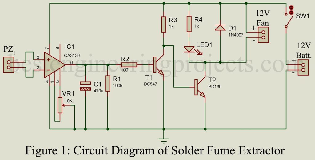
For automation of the project’s solder fumes extractor, we have used a sensor called a piezo sensor (PZ1). The sensor PZ1 generates a voltage when heat is detected (heat generates stress in it). Thus, we attached a heat sink with piezo sensor PZ1. The PZ1 is connected to two inputs (inverting and non-inverting) of IC1 as shown in figure 1.
The heat sink connected to piezo sensor PZ1 is kept near the soldering stand. For a better description, we have divided the working of the solder fumes extractor circuit into two cases.
CASE I: When soldering iron is on a soldering stand, the heat from soldering built stress on the piezo sensor as a result voltage of 1V generates to the piezo sensor which activates op-amp and the output of op-amp becomes high. The high output of op-amp turns transistor T1 ON and transistor T2 OFF as a result fan connected to the circuit is switched OFF.
CASE II: when the soldering iron is taken out from the soldering stand to solder a joint, no stress is built on the piezo sensor due to heat as a result of the output of op-amp drive transistor T1 to the off state, but transistor T2 starts to conduct which further switch on the fan which removes fumes from soldering.
Null adjustment of IC1 is adjustment by variable resistor VR1. When the output of IC1 is momentarily low the capacitor C1 makes transistor T1 on and is discharged through resistor R1 when the output of IC1 becomes low.
You can also look for Temperature controlled soldering iron station
PARTS LIST OF SOLDER FUMES EXTRACTOR CIRCUIT USING OP-AMP
| Resistors (all ¼-watt, ± 5% Carbon) |
| R1 = 100 KΩ
R2 = 100 Ω R3, R4 = 1 KΩ VR1 = 10 KΩ |
| Capacitor |
| C1 = 470 µF, 35V (Electrolytic Capacitors) |
| Semiconductors |
| IC1 = CA3130 op-amp
T1 = BC547 (NPN transistor) T2 = BD139 (NPN transistor) D1 = 1N4007 (general purpose rectifier diode) LED1 = 3mm any color LED |
| Miscellaneous |
| PZ1 = Piezo sensor
SW1 = ON/OFF Switch 12V DC Exhaust Fan Batt. = 12V, 7Ah Battery Heat sink |