The majority of Microcontroller Units (MCU) include a limited amount of storage space that is adequate to hold your code or software. The Arduino Mega (ATmega2560) has 8 KB of bootloader space, 256 KB of flash memory for code storage, 8 KB of SRAM, and 4 KB of EEPROM (which can be read and written with the EEPROM library). The issue now is what to do if you need to store data for applications like data loggers, data visualization, etc., but the microcontroller unit memory is too small to be taken into consideration and only should be used to store your code. We need to use external memory to solve this issue, and SD cards are among the popular choices. Thus this article will quench your thirst for a Micro SD card module and Arduino interface.
SD (Secure Digital) is a non-volatile memory card popular due to its portability. Even among the different types of SD cards, microSD cards are used extensively in microcontroller applications due to their miniature size having a form factor of 15 mm × 11 mm × 1 mm. Too Facilitate communication between a microSD card and an Arduino board microSD card module is required, which should be easily accessible in the market.
Hardware Overview of MicroSD card module

Figure: Micro SD Card Module Front and Back Side
A MicroSD card mainly consists of three main components:
- 3.3V LDO Voltage Regulator: The operating voltage of a standard microSD card is 3.3V, and a voltage greater than 3.6V will permanently damage the SD card. Thus, the module contains a 3.3V low dropout voltage regulator to provide a proper power supply to the SD card and to prevent damage from the 5V logic circuit.
- Logic level shifter chip (74LVC125A): It resolves any issues that arise due to voltage incompatibility between the SD card module and a microcontroller.
- MicroSD card Connector: It holds the microSD card and allows easy card insertion and removal.
MicroSD Card Module Pin Layout
| S.No. | Pin Type | Pin Description |
| 1 | VCC | Voltage Input |
| 2 | GND | Ground |
| 3 | MISO | Master In Slave Out (SPI Output) |
| 4 | MOSI | Master Out Slave In (SPI Input) |
| 5 | SCK | Serial Clock |
| 6 | CS | Chip select |
Micro SD Card Module and Arduino Interface
The first step is to correctly format the microSD card to FAT16 or FAT32 before placing it in the module. Afterward, connect the module VCC and GND pin to the 3.3V or 5V pin and GND pin of the Arduino respectively.

Interfacing of the SD card module with Arduino is done with Serial Peripheral Interface (SPI). The SPI pins of the module are connected to the Arduino’s SPI pins. Different models of Arduino boards have different SPI pins, so ensure that SPI pins are connected correctly.
SPI pins of Arduino mega, Arduino uno, and Arduino nano
| S.No. | Pin Type | Arduino mega | Arduino uno | Arduino nano |
| 1 | MISO | 50 | 12 | 12 |
| 2 | MOSI | 51 | 11 | 11 |
| 3 | SCK | 52 | 13 | 13 |
| 4 | CS | 53 | 4 | 4 |
Preparation of SD Card
To prepare the SD card for interfacing, we have to format it in the right system. Initially, though the SD card is formatted in the FAT file system but it might not work. For proper working of SD card, you have to format it into FAT16 or FAT32 system.
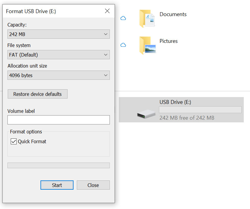
Figure: Micro SD card Format in FAT system
Arduino Code
First program: Testing the SD card
Arduino IDE provides an in-built Cardinfo Sketch to test your SD card. When Sketch is uploaded to the Arduino depending upon the output displayed on the serial monitor you may infer the following things.
- SD card is working properly or not
- SD card is corrupted or not
- SD card is properly formatted or not
Before Uploading the sketch, verify that the CS(chip select) pin is initialized correctly.
To open the CardInfo example sketch, navigate to File > Examples > SD > CardInfo.
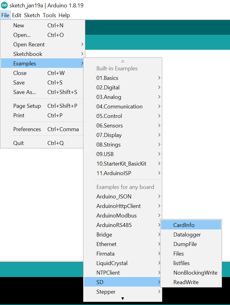 Figure: Arduino example for SD card
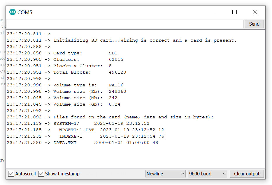
Figure: SD card information
After successfully verifying the SD card, we are ready to perform the read-and-write operation.
|
1 2 3 4 5 6 7 8 9 10 11 12 13 14 15 16 17 18 19 20 21 22 23 24 25 26 27 28 29 30 31 32 33 34 35 36 37 38 39 40 41 42 43 44 45 46 47 48 49 50 51 52 53 54 55 56 57 |
#include <SPI.h> #include <SD.h> <span style="font-weight: 400;">const</span> <span style="font-weight: 400;">int</span><span style="font-weight: 400;"> chipSelect = 4</span><span style="font-weight: 400;">;</span> File myFile; void setup() { // Open serial communications and wait for port to open: Serial.begin(9600); while (!Serial) { ; // wait for serial port to connect. Needed for native USB port only } Serial.print("Initializing SD card..."); if (!SD.begin(<span style="font-weight: 400;">chipSelect</span>)) { Serial.println("initialization failed!"); while (1); } Serial.println("initialization done."); // open the file. note that only one file can be open at a time, // so you have to close this one before opening another. myFile = SD.open("test.txt", FILE_WRITE); // if the file opened okay, write to it: if (myFile) { Serial.print("Writing to test.txt..."); myFile.println("testing 1, 2, 3."); // close the file: myFile.close(); Serial.println("done."); } else { // if the file didn't open, print an error: Serial.println("error opening test.txt"); } // re-open the file for reading: myFile = SD.open("test.txt"); if (myFile) { Serial.println("test.txt:"); // read from the file until there's nothing else in it: while (myFile.available()) { Serial.write(myFile.read()); } // close the file: myFile.close(); } else { // if the file didn't open, print an error: Serial.println("error opening test.txt"); } } void loop() { // nothing happens after setup } |
After the Sketch is uploaded serial monitor will display
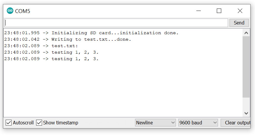
Figure: SD card Read and Write output
Code Explanation
|
1 2 3 4 5 |
#include <SPI.h> #include <SD.h> // change this according to CS pin; const int chipSelect = 4; File myFile; |
This code block starts with importing the SD and SPI library which enables the communication between the SD module and Arduino through the SPI interface.
Next, comes the definition CS (chip select) pin, and other SPI pins are defined in the library as we are using hardware interrupt. Finally, we declare our file object to access the methods for read and write operations.
|
1 2 3 4 5 6 7 8 9 10 11 12 13 14 15 |
// Open serial communications and wait for the port to open: Serial.begin(9600); while (!Serial) { ; } Serial.print("Initializing SD card..."); if (!SD.begin(chipSelect)) { // If SD card is not detected and program terminates Serial.println("initialization failed!"); return; } // If SD card is detected Serial.println("initialization done."); |
This block of code simply checks if the SD is recognized or not after the Serial monitor is up and running.
|
1 2 3 4 5 6 7 8 9 10 11 12 13 14 15 |
// open the file. note that only one file can be open at a time, // so you have to close this one before opening another. myFile = SD.open("test.txt", FILE_WRITE); // if the file opened okay, write to it: if (myFile) { Serial.print("Writing to test.txt..."); myFile.println("testing 1, 2, 3."); // close the file: myFile.close(); Serial.println("done."); } else { // if the file didn't open, print an error: Serial.println("error opening test.txt"); } |
This block of code performs the write operation on the file and if the file cannot be opened an error message is displayed on the serial monitor. Here, open() function is used to open the file. File can be opened in different modes two modes mentioned in this code are
- FILE_WRITE (opens the file for reading and writing and places the cursor at the end of the file).
- FILE_READ (opens the file for reading and places the cursor at the beginning of the file)
To write on a file it must be open in write mode and println() function can be used to write on the file. After the write operation, we must close the file which is accomplished by calling close() methods on file objects.
|
1 2 3 4 5 6 7 8 9 10 11 12 13 14 15 16 |
// re-open the file for reading: myFile = SD.open("test.txt"); if (myFile) { Serial.println("test.txt:"); // read from the file until there's nothing else in it: while (myFile.available()) { Serial.write(myFile.read()); } // close the file: myFile.close(); } else { // if the file didn't open, print an error: Serial.println("error opening test.txt"); } } |
This block of code opens the file in read mode and prints every character on the serial monitor. Here, the read() function reads a single character at a time so a while loop is used to read all the characters of the file.