Transistors and diodes are fundamental components in electronics and play a significant role in many circuit designs. When it comes to incorporating these active components into a circuit, it’s crucial to ensure that they are working correctly. Therefore, it’s essential to have a reliable method to test transistors and diodes.
Circuit Description of Transistor and Diode Tester using 555 IC
In this article, we will discuss a simple yet effective transistor and diode testing circuit that can help you identify whether these components are functioning correctly or not. The circuit uses the versatile and reliable LM555 timer IC as a multivibrator that generates a 70 Hz frequency with the help of resistors R1 and R2 and capacitor C1.
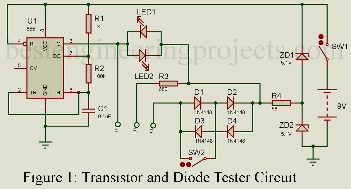
To test a transistor, switch SW2 must be in the off mode. In the absence of a testing transistor, both LEDs will flash. However, when you connect a PNP or NPN transistor to the test terminals B, C, and E, the voltage drop across one of the LEDs becomes lower than the threshold voltage, which causes one LED to stop glowing. This indicates that the transistor is good. If both LEDs remain lit, it means that the transistor is faulty and has either a short-circuited or broken collector-emitter junction.
Diode testing is equally simple. Push SW2 on, and connect the diode under test between the C and E terminals. If the diode is functioning correctly, one LED will light up, but if it is faulty, all LEDs will light up.
One of the primary advantages of this circuit is its simplicity. Even if you’re a beginner in electronics, you should be able to understand and build this circuit with ease using the LM555 timer IC, resistors, capacitors, LEDs, and switches.
In conclusion, having a reliable method to test transistors and diodes is critical in electronics. The circuit we have discussed in this article is an easy and efficient way to test these components, which can help you ensure that your circuits are functioning correctly. By incorporating this circuit into your electronics projects, you can avoid costly and time-consuming errors.
COMPONENT LIST OF TRANSISTOR AND DIODE TESTER
Resistors (all ¼-watt, ± 5% Carbon)
R1 = 1 KΩ
R2 = 100 KΩ
R3 = 680 Ω
R4 = 68 Ω
Capacitor
C1 = 0.1 µF
Semiconductors
u1 = NE555 timer IC
D1 – D4 = 1N4148
ZD1, ZD2 = Zener diode 5.1 Volt
LED1, LED2 = LEDs of different color
Miscellaneous
SW1, SW2 = switch
9V battery for power supply
Interesting circuit.