An AC mains voltage indicator circuit is a very useful device that indicates the different levels of the mains voltage. This circuit utilizes three different LEDs to indicate the different ranges of voltage i.e. Low, Nominal, and High. It is important to know this information when you are working with electrical equipment because it can help you ensure that everything is working properly and that you are not overloading the circuit.
Fortunately, you don’t need to be an electrical expert to build an AC mains voltage indicator. In fact, even school students can make one! The circuit is very simple and easy to assemble, and it requires just a few basic components.
Description of AC Mains Voltage Indicator Circuit
The circuit consists of three transistors (T1, T2, and T3), three potentiometers (VR1, VR2, and VR3), and three different colored lights (LEDs). The transistors and potentiometers are used to control the amount of electricity that flows through the circuit, while the LEDs are used to indicate the voltage level.
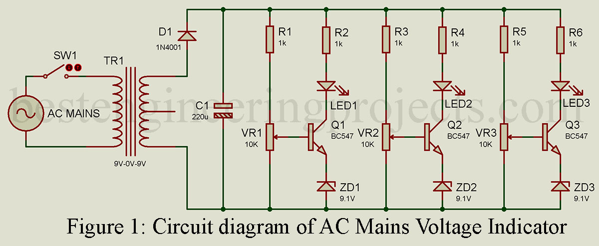
All three LEDs in this AC mains voltage indicator are connected between collectors of transistors T1, T2, and T3 respectively. Here potentiometers VR1, VR2, and VR3 are used to adjust the base voltage of transistors T1, T2, and T3 respectively. As shown in the circuit diagram of the AC mains voltage indicator first AC mains is stepped down by a 9V-0-9V transformer and then rectified by a signal diode D1 and smoothed by C1 which gives output 25V DC. This circuit is work on the principle, when AC mains vary DC voltage also varies proportionally and is sensed by transistors T1 through T3.
For setting the low-level voltage, a manual AC voltage regulator (MVR) should be connected to the primary coil of transformer X1. Now set the AC voltage of MVR to about 175V and slowly potentiometer VR1 adjusted until the voltage across the base of transistor T1 reaches 9.7V and the transistor starts conducting which glows LED1 and stops glowing when the base voltage drops below the preset value. This process is repeated for 200V and 230V in which LED2 and LED3 glow respectively.
Now connect this circuit to AC mains, if the voltages drop below 175 volts no LEDs glow. First, a high voltage (more than 230V) is indicated by all three LEDs glowing (LED1, LED2, LED3). Second, normal voltage (200V-230V) is indicated by two LEDs (LED1 and LED2). Third, a low voltage (175V-200V) is indicated by the glowing LED1 only.
Once you have built the circuit, you can use it to measure the voltage level of your outlets. If the voltage is too low, none of the LEDs will light up. If the voltage is very high, all three LEDs will light up. And if the voltage is just right, two of the LEDs will light up.
Using this circuit is safe and easy, and it can help you ensure that your electrical equipment is working properly. With just a few basic components, you can build your own AC mains voltage indicator and start measuring the voltage levels in your home or classroom!
Component List of AC Mains Voltage Indicator Circuit
Resistors (all ¼-watt, ± 5% Carbon)
R1– R6= 1 KΩ
VR1 – VR3 = 10 KΩ
Capacitor
C1 = 220 µF/50V
Semiconductors
T1 – T3 = BC547
ZD1 – ZD3 = 9.1V zener diode
D1 = 1N4001
LED1 – LED3 = 5mm different color LED
Miscellaneous
X1 = 230V AC primary to 9V-0-9V, 250mA secondary transformer
SW1 = On/off switch
Good informated