Digital circuits are an essential part of modern technology, and they power everything from smartphones to computers. However, detecting faults and troubleshooting digital circuits can be challenging, especially for those who are new to electronics. Here, we present a simple and versatile digital circuit tester that can help you identify problems in your circuits quickly and easily.
Description of Digital Circuit Tester using 4049 IC
The digital circuit tester described in this article is built around a CMOS hex inverter buffer CD4049 that contains six independent inverters labeled a-f. Inverter A forms a basic integrator, while inverter B and C form a Schmitt trigger. Presets VR1 and VR2 control the frequency of the square wave oscillator and adjust the duty cycle to 50%, respectively. The output of each inverter is fed to another inverter, and inverters d and e produce complementary output. The output from the complementary pair (inverter D and E) is used to drive two LEDs (LED1 and LED2), with resistor R6 used as the current limiter.
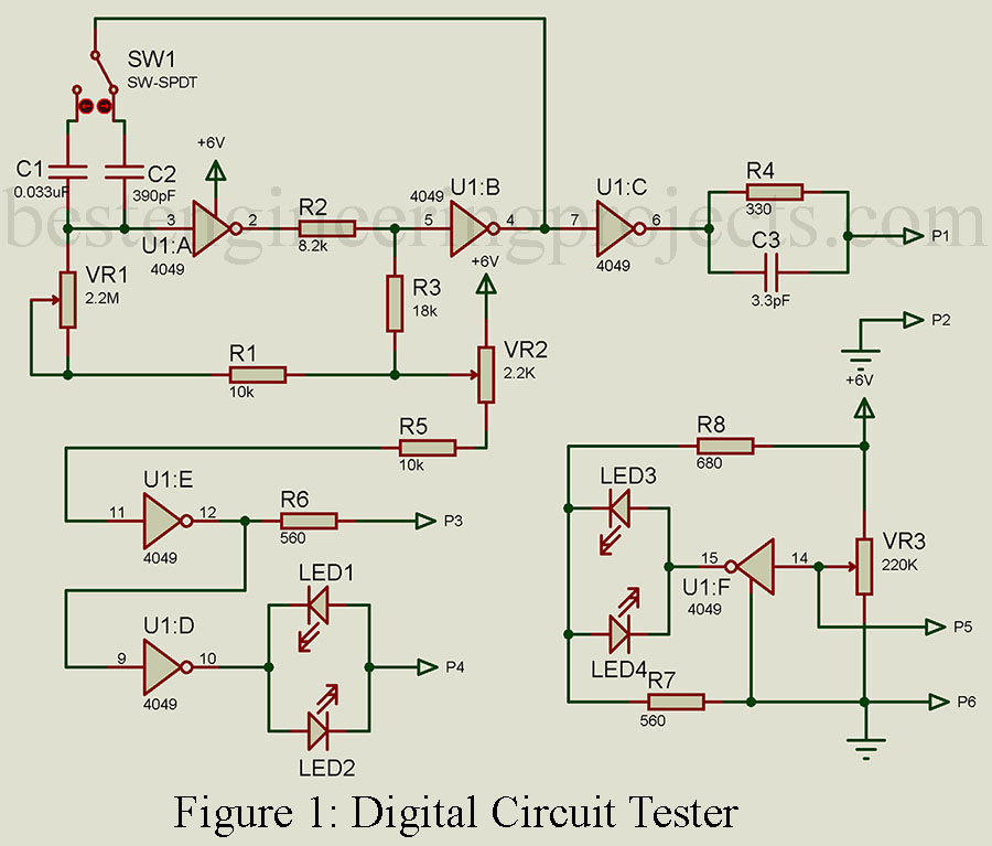
One of the key advantages of this digital circuit tester is its ability to detect logic states. Inverter f is designed to detect logic states, with LED3 and LED4 indicating high and low logic states, respectively, depending on the logic condition at probe P5 with respect to probe P6. The transitional point (where the LEDs switch off) is adjusted by preset VR3.
To use the tester, first, generate the frequency from probes P1 and P2, which is set by preset VR1. The frequency range is 10 Hz to 1 KHz in the LF position and 1 KHz to 70 KHz in the HF position. The LF and HF positions are selected by switch SW1. Next, use probes P3 and P4 to test semiconductors and their direction (forward bias and reverse bias). The LED’s direction indicates the forward bias of the semiconductor. A glowing LED indicates that the component is functioning properly and indicates its polarity. The resistive component can also be tested through probes P3 and P4, with both LEDs glowing indicating the component is functioning.
Finally, use probes P5 and P6 to test the logic state, with probe P6 connected to the ground of the circuit under test. The supply voltage must be 6V. By using this digital circuit tester, you can quickly identify problems in your circuits and troubleshoot them effectively.
In conclusion, the digital circuit tester presented in this article is a simple and versatile tool that can help you detect faults and troubleshoot digital circuits easily. By using this tester, you can save time and effort, and quickly identify the root cause of the problem. Whether you are a hobbyist or a professional, this digital circuit tester can be an invaluable addition to your toolkit.
COMPONENT LIST OF DIGITAL CIRCUIT TESTER
Resistors (all ¼-watt, ± 5% Carbon)
R1, R5, = 10 KΩ
R2 = 8.2 KΩ
R3 = 18 KΩ
R4 = 330 Ω
R6, R7 = 560 Ω
R8 = 680 Ω
VR1 = 2.2 MΩ
VR2 = 2.2 KΩ
VR3 = 220 KΩ
Capacitors
C1 = 0.033 µF
C2 = 390 pF
C3 = 3.3 pF
Semiconductors
IC1 = CD4049B
Miscellaneous
SW1 = Single pole double throw (SPDT) switch
SW2 = Push to ON/OFF switch
LED1 – LED4 = Different Color LEDs