Long-distance communication (or constant data transmissions) has become essential to modern industries, the medical sector, and even the residential sector. These data include the status/outputs of sensors, operation logs of machines, images or videos, scheduled events, etc. Transferring these data between machines via wired or wireless medium without human input is called Machine-to-Machine communication (M2M). The same communication using a cloud platform instead of point-to-point becomes IoT. Realizing the growing demand for faster, more secure, and more efficient communication, technologies that enable long-range wireless communication were developed. Of many, “LoRa” stood out by satisfying the need for low power consumption, higher communication range, interference immunity, mobility, and energy efficiency. It was designed for sensor data transmission at low speeds (around 20-50 Kbps).
In this article, we will interface Arduino Nano and a transponder module called LoRa SX1278 (which utilizes the patented “LoRa” modulation technique). After interfacing the module, we will also learn to transmit data between two LoRa sensor nodes. For example, we will use the DHT11 sensor to transmit humidity and temperature data.
After completing this article, you will be able to:
- Interface the LoRa-02 module with Arduino Nano.
- Transmit sensor data between LoRa nodes.
- Display the readings on the LCD.
Introduction to “LoRa”:
“LoRa,” meaning “Long Ranged,” is a well-known radio communication method. LoRa in itself is a physical layer protocol that is derived from Chirp Spread Spectrum (CSS). CSS is a wideband linear frequency modulation in which carrier frequency varies for the defined extent of time. A chirp is a sinusoidal signal whose frequency increases or decreases over time (often with a polynomial relationship between time and frequency). Due to this, CSS is ideal for applications requiring low power usage with lower data rates (<1 Mbit/s), longer ranges, and when devices moving at high speeds are part of your network.
The “LoRa module” supports different ISM band frequencies, namely 868MHz (Europe), 915MHz (North America), and 433MHz (Asia), and encodes information on radio waves using chirp pulses. So, we can conclude that LoRa targets key Internet of Things (IoT) requirements such as bidirectional communication, end-to-end security, mobility, and localization services.
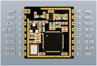
Figure 1: LoRa SX1278 Module
This article will use a specific LoRa SX1278 module consisting of a “Ra-02” chip from AI-Thinker. This chip supports the ISM band of range 410-525MHz, a Power amplifier (PA) of +18dBm, and LoRa/FSK/OOK modulation techniques. The features and Specification of the whole package are given as follows:
Features of SX1278 LoRa:
- works in ISM bands (Industrial Standard Medical band)
- Half-duplex SPI communication
- Low powered consumption
- High-range coverage (~10Km)
- Operates on low bandwidth
- Supports Preamble detection
- excellent blocking and interference immunity
- Built-in temperature sensor and battery indicator.
- Built-in bit synchronizer for clock recovery
Specification:
- Module Model: Ra-02
- Package: SMD-16
- Size/Dim: 17*16*(3.2 ± 0.1) mm
- Programmable bit rate up to 300 kbps
- Frequency Range: 410 MHz – 525 MHz
- Operating temperature: -30℃ to 85℃
- Power Supply: 2.5 ~ 3.7V (Typically : 3.3V)
- industry-leading 168dB max Link budget
- High sensitivity: down to -148 dBm
- +20 dBm (i.e ~ 100 mW) RF transmit power
- can use FSK, GFSK, MSK, GMSK, OOK, and LoRa (default) modulation
- Low RX current of 9.9 mA, 200 nA register retention
- Bullet-proof front end: IIP3 = -11 dBm
- 127dB RSSI Dynamic Range
Components Required
Arduino Nano x 2
LoRa-2 SX1278 x 2
DHT11 (Hum & Temp) x 1
16X2 – I2C LCD display x 2
Interfacing Sx1278 with Nano:
The table below describes the wiring between I2C_LCD, LoRa, and Nano for the transmitter and receiver nodes.
As the figures below demonstrate, the I2C_LCD has its VCC & GND pin connected to 5V & ground, whereas its SDA & SCL pin to analog pins A4 & A5 of Nano.
For LoRa and Nano interfacing, the following is given below:
| LoRa-02 SX1278 | NANO pins |
| VCC (3.6V max) | 3.3V |
| GND | GND |
| SCK (SPI clock) | D13 |
| DIO0 (Digital I/O) | D2 |
| RST (Reset) | D9 |
| NSS (Chip select) | D10 |
| MOSI (SPI data input) | D11 |
| MISO (SPI data output) | D12 |
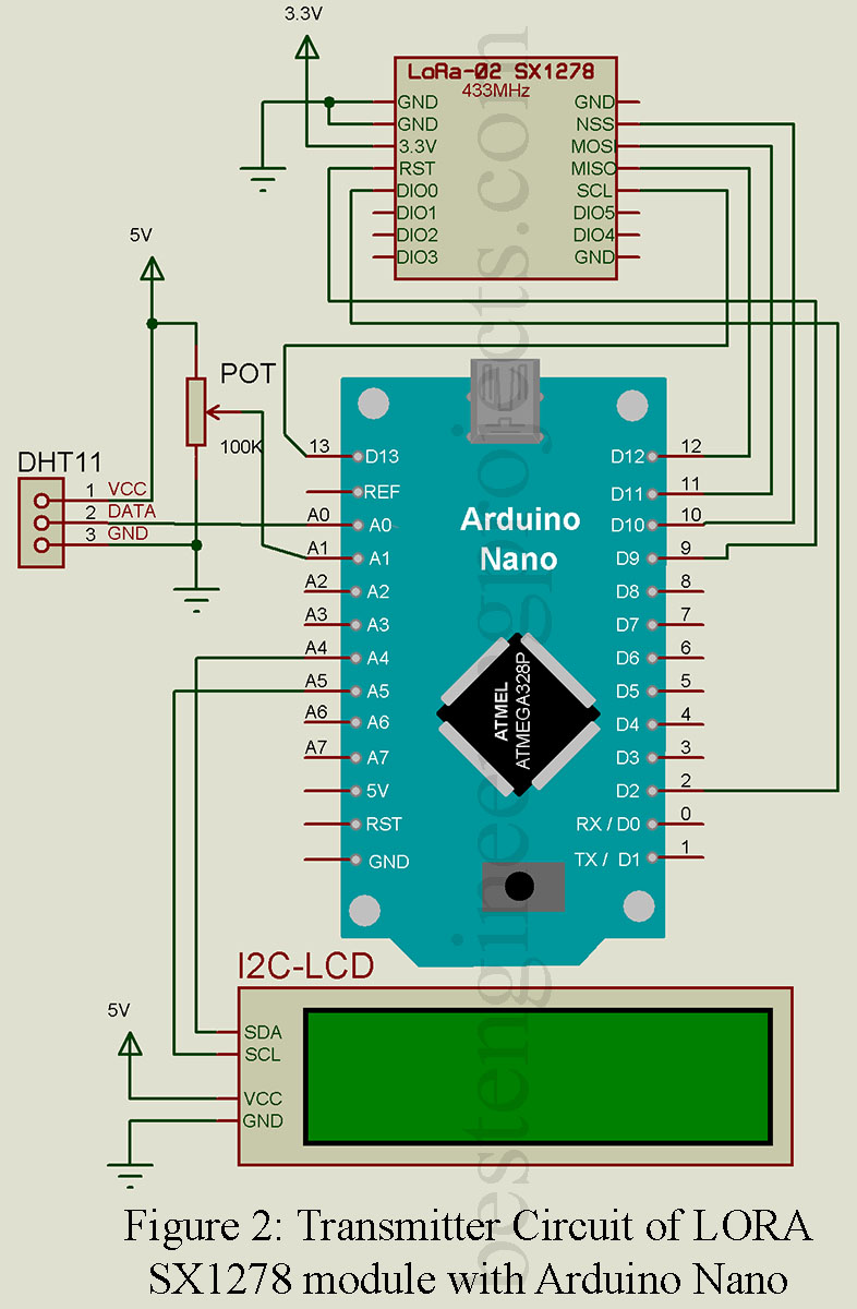
Use 3.3V of Arduino Nano to connect it to the VCC pin of the LoRa module. Connect all the GND pins to GND. Connect the RST pin to D9 and DIO0 to D2 of Arduino. As shown in the circuit diagram above, connect the SPI Pins NSS, MOSI, MISO, and SCK to Arduino D10, D11, D12, and D13 Arduino. Then, the VCC, DATA & GND pins of the DHT11 (humidity & temperature) sensor are connected to the 5V, D3, and GND pins of Nano, respectively, as shown above.
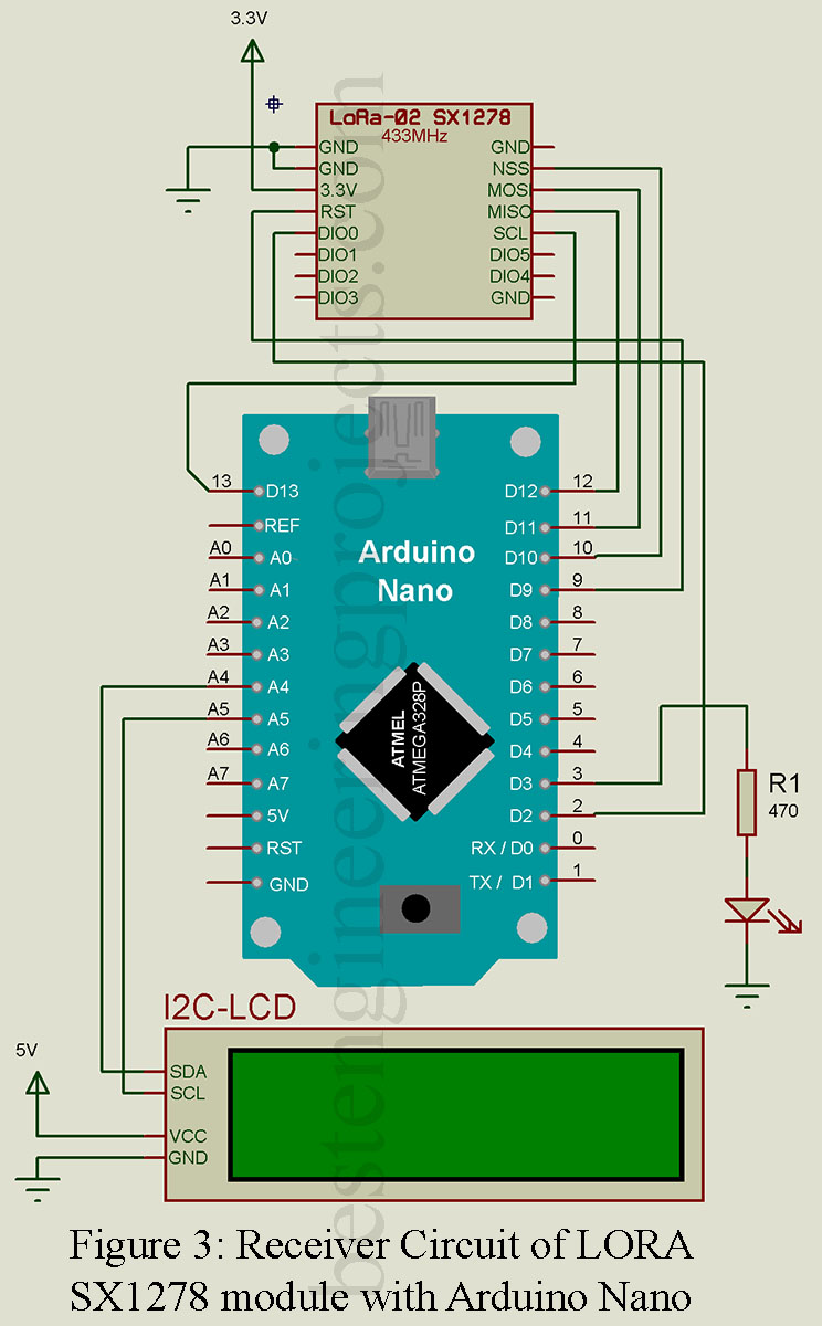
Use 3.3V of Arduino Nano to connect it to the VCC pin of the LoRa module. Connect all the GND pins to GND. Connect the RST pin to D9 and DIO0 to D2 of Arduino. As shown in the circuit diagram above, connect the SPI Pins NSS, MOSI, MISO, and SCK to Arduino D10, D11, D12, and D13 Arduino. Then connect the D3 pin of nano to the cathode of LED and then to gnd via a 470Ω resistor as shown.
How to transmit Sensor Data:
Firstly, we require two libraries to operate the LoRa-02 SX1278 module via the Nano, namely <SPI.h> and <LoRa.h>. The “SPI.h” library is responsible for serial communication between module and nano, whereas “LoRa.h” is responsible for transmitting/Receiving operations.[Note: This “LoRa.h” library allows you to send data to any radios in range with the same radio parameters. All data are broadcasted without any addressing.]. We are using DHT11(temperature & humidity sensor) for the sensor. So the <DHT.h> library is required to extract the temperature and humidity data captured by the DHT11 sensor.
After successfully interfacing all the hardware as instructed, the step-by-step explanation of the code for sensor data reading and transmission process is given below:
Software Code
Transmitter Side Code
Including necessary libraries:
Three libraries, DHT.h, SPI.h, and LoRa.h, are included for sensor data generation/reading. They serially transfer that data from Nano to the LoRa module and then transmit it.
|
1 2 3 4 5 |
#include <SPI.h> #include <LoRa.h> #include <DHT.h> |
Defining important parameters:
Here, the incoming data from DHT11 is assigned to digital pin D3 of nano. We also have to specify the sensor model type while initializing the sensor. Then, two variables, humidity and temperature data, are required.
|
1 2 3 4 5 6 7 8 9 |
#define DHTPIN A0 #define DHTTYPE DHT11 DHT dht(DHTPIN, DHTTYPE); // initialize the sensor int hum; //Stores humidity value float temp; //Stores temperature value |
Initialize Setup Function:
Here, we initialize the LoRa library with a 433MHz frequency using LoRa.begin(). This function also scans whether a message has been sent. If not, it displays” Starting LoRa failed!”
|
1 2 3 4 5 6 7 8 9 10 11 12 13 14 15 16 17 18 19 20 21 22 23 |
void setup() { Serial.begin(9600); dht.begin(); while (!Serial); Serial.println("LoRa Sender"); if (!LoRa.begin(433E6)) // initialize the LoRa 433E6 => 433Mhz { Serial.println("Starting LoRa failed!"); while (1); } } |
Read and transmit sensor Data:
Read the temperature and humidity data using “dht” objects and store them into respective variables. Then, transmit them using the LoRa.print() function. The transmitted message ends with a “*” character, which the receiver uses to break the combined serial characters into a meaningful message.
|
1 2 3 4 5 6 7 8 9 10 11 12 13 14 15 16 17 18 19 20 21 22 23 24 25 26 27 28 |
void loop() { temp = dht.readTemperature(); hum = dht.readHumidity(); Serial.println("........................."); Serial.println("Sending packet: "); // send Humidity packet LoRa.beginPacket(); //Start the sequence of sending a packet. LoRa.print("Humidity: "); LoRa.print(hum); LoRa.print("%"); LoRa.print(" Temperature:"); LoRa.print(temp); LoRa.print("C"); LoRa.print("*"); //this indicates the end of sending string //Display sent data in serial monitor Serial.print("Humidity: "); Serial.print(hum); Serial.print("%"); Serial.print(" Temperature:"); Serial.print(temp); Serial.println("C"); Serial.println(""); LoRa.endPacket(); delay(500); } |
After the transmission is done, a step explanation of the code performing the data reception process is given below:
Receiver Side Code
Initialize the necessary libraries and parameters:
We include the SPI.h and LoRa.h libraries for serial communication and LoRa module operations. Then a String type variable (inString) captures the incoming character and merges them into one string. The counter is the count no of captured characters.
|
1 2 3 4 5 6 7 |
#include <SPI.h> #include <LoRa.h> String inString = ""; // string to hold input int counter = 0; // to count no of characters |
Initialize the Setup function:
Here, we initialize the LoRa library with a 433MHz frequency using LoRa.begin(). This function scans whether a message has been sent. If not, it displays “Starting LoRa failed!”
|
1 2 3 4 5 6 7 8 9 10 11 12 13 14 15 16 17 18 19 |
void setup() { Serial.begin(9600); while (!Serial); Serial.println("LoRa Receiver"); if (!LoRa.begin(433E6)) { Serial.println("Starting LoRa failed!"); while (1); } } |
Void loop:
Here, we will check if a packet has been received using “LoRa.parsePacket().” This function returns the packet size in bytes or 0 if no packet was received. Then, read the characters and append them to a string variable (inString). Then, display the message/combined data in the serial monitor. If the “*” character is received, it indicates the end of the message.
|
1 2 3 4 5 6 7 8 9 10 11 12 13 14 15 16 17 18 19 20 21 22 23 24 25 26 27 28 29 |
void loop() { // try to parse packet int packetSize = LoRa.parsePacket(); if (packetSize) // continue if packet is received { // received a packet Serial.println(""); Serial.println("..................................."); Serial.println("Received packet: "); // read packet inString = ""; while (LoRa.available()) { char incoming = (char)LoRa.read(); //read each chr if( incoming == '*') { break; } //breaks the appending action; if '*' inString += incoming; //append all chr counter ++; } } //if any string is captured if (counter>0) { Serial.println(inString); //display in monitor } counter =0; } |
Complete Code:
|
1 2 3 4 5 6 7 8 9 10 11 12 13 14 15 16 17 18 19 20 21 22 23 24 25 26 27 28 29 30 31 32 33 34 35 36 37 38 39 40 41 42 43 44 45 46 47 48 49 50 51 52 |
/* *** Transmitter Code*** */ #include <SPI.h> #include <LoRa.h> #include <DHT.h> #define DHTPIN A0 #define DHTTYPE DHT11 DHT dht(DHTPIN, DHTTYPE); int hum; float temp; //Stores temperature value void setup() { Serial.begin(9600); dht.begin(); while (!Serial); Serial.println("LoRa Sender"); if (!LoRa.begin(433E6)) // 433Mhz { Serial.println("Starting LoRa failed!"); while (1); } } void loop() { temp = dht.readTemperature(); hum = dht.readHumidity(); Serial.println("........................."); Serial.println("Sending packet: "); // send Humidity packet LoRa.beginPacket(); LoRa.print("Humidity: "); LoRa.print(hum); LoRa.print("%"); LoRa.print(" Temperature:"); LoRa.print(temp); LoRa.print("C"); //Display sent data in serial monitor Serial.print("Humidity: "); Serial.print(hum); Serial.print("%"); Serial.print(" Temperature:"); Serial.print(temp); Serial.println("C"); Serial.println(""); LoRa.endPacket(); delay(500); } |
|
1 2 3 4 5 6 7 8 9 10 11 12 13 14 15 16 17 18 19 20 21 22 23 24 25 26 27 28 29 30 31 32 33 34 35 36 37 38 39 40 41 42 43 44 |
/* *** Receiver Code*** */ #include <SPI.h> #include <LoRa.h> String inString = ""; // string to hold input int counter = 0; // to count no of characters void setup() { Serial.begin(9600); while (!Serial); Serial.println("LoRa Receiver"); if (!LoRa.begin(433E6)) { Serial.println("Starting LoRa failed!"); while (1); } } void loop() { // try to parse packet int packetSize = LoRa.parsePacket(); if (packetSize) // continue if packet is received { // received a packet Serial.println(""); Serial.println("..................................."); Serial.println("Received packet: "); // read packet inString = ""; while (LoRa.available()) { char incoming = (char)LoRa.read(); //read each chr inString += incoming; //append all chr counter ++; } } //if any string is captured if (counter>0) { Serial.println(inString); //display in monitor } counter =0; } |
Displaying the Sensor Data in LCD
The transfer of sensor data has been modified and displayed in LCD. The code is as follows:
Transmitter Code:
|
1 2 3 4 5 6 7 8 9 10 11 12 13 14 15 16 17 18 19 20 21 22 23 24 25 26 27 28 29 30 31 32 33 34 35 36 37 38 39 40 41 42 43 44 45 46 47 48 49 50 51 52 53 54 55 56 57 58 59 60 61 62 63 64 65 66 67 68 69 70 71 72 73 74 75 76 77 78 79 80 |
#include <SPI.h> #include <LoRa.h> #include <DHT.h> #include <LiquidCrystal_I2C.h> //specifyting LiquidCrystal_I2C lcd(0x27,16,2); #define DHTPIN A0 #define DHTTYPE DHT11 DHT dht(DHTPIN, DHTTYPE); int hum; float temp; //Stores temperature value void setup() { Serial.begin(9600); //initialize the LCD display lcd.init(); lcd.backlight(); lcd.clear(); lcd.print("LoRa"); lcd.setCursor(0,1); lcd.print("Sender"); delay(2000); dht.begin(); //while (!Serial); //Serial.println("LoRa Sender"); if (!LoRa.begin(433E6)) // 433Mhz { Serial.println("Starting LoRa failed!"); while (1); } } void loop() { temp = dht.readTemperature(); hum = dht.readHumidity(); LoRa.beginPacket(); Serial.println("........................."); Serial.println("Sending packet: "); // send Humidity packet LoRa.print(hum); LoRa.print("%"); LoRa.print(temp); LoRa.print("C"); LoRa.print("*"); //Display in LCD lcd.clear(); lcd.setCursor(0,0); lcd.print("Hum:"); lcd.setCursor(4,0); lcd.print(hum); lcd.setCursor(7,0); lcd.print("%"); lcd.setCursor(0,1); lcd.print("Temp:"); lcd.setCursor(5,1); lcd.print(temp); lcd.setCursor(10,1); lcd.print((char)0xDF); // displaying the “degree” symbol lcd.print("C"); //Display sent data in serial monitor Serial.print("Humi: "); Serial.print(hum); Serial.println("%"); Serial.print("Temp: "); Serial.print(temp); Serial.println("C"); Serial.println(""); LoRa.endPacket(); delay(1000); } |
Receiver Code:
|
1 2 3 4 5 6 7 8 9 10 11 12 13 14 15 16 17 18 19 20 21 22 23 24 25 26 27 28 29 30 31 32 33 34 35 36 37 38 39 40 41 42 43 44 45 46 47 48 49 50 51 52 53 54 55 56 57 58 59 60 61 62 63 64 65 66 67 68 69 70 71 72 73 74 75 76 77 78 79 80 81 82 83 84 85 86 87 88 89 90 91 92 93 94 95 96 97 98 99 100 101 102 103 104 105 |
#include <SPI.h> #include <LoRa.h> #include <LiquidCrystal_I2C.h> //specifyting LiquidCrystal_I2C lcd(0x27,16,2); String inString = ""; // string to hold input String Humi ; // string to hold Humidity input String Temp ; // string to hold Temperature input int counter = 0; void setup() { Serial.begin(9600); //pinMode(LED,OUTPUT); //initialize the LCD display lcd.init(); lcd.backlight(); lcd.clear(); lcd.print("LoRa"); lcd.setCursor(0,1); lcd.print("Receiver"); delay(2000); //setup LoRa //while (!Serial); //Serial.println("LoRa Receiver"); if (!LoRa.begin(433E6)) { Serial.println("Starting LoRa failed!"); while (1); } } void loop() { // try to parse packet int packetSize = LoRa.parsePacket(); if (packetSize) { // received a packet Serial.println(""); Serial.println("..................................."); Serial.println("Received packet: "); // read packet inString = ""; Humi = ""; Temp = ""; while (LoRa.available()) { char incoming = (char)LoRa.read(); //read a chr if( incoming == '*') {break;} //breaks the appending action at '*' inString += incoming; counter ++; } } //if any string is captured if (counter>0) { //create str buffer char str[counter+1] ; //Copy it over inString.toCharArray(str, counter+1); //int flag = 0 ; for (int i=0;i<=counter;i++) { char c = str[i]; Serial.print(c); if (i<2 and c!='%'){Humi += c; } else if (i>2 and c!='%' and c!='C' and i<9){Temp +=c;} } //display in LCD lcd.clear(); lcd.setCursor(0,0); lcd.print("Hum:"); lcd.setCursor(4,0); lcd.print(Humi); lcd.setCursor(7,0); lcd.print("%"); lcd.setCursor(0,1); lcd.print("Temp:"); lcd.setCursor(5,1); lcd.print(Temp); lcd.setCursor(10,1); lcd.print((char)0xDF); // displaying the “degree” symbol lcd.print("C"); //Serial display Serial.println(""); Serial.print("HUM: "); Serial.print(Humi); Serial.println("%"); Serial.print("Temp: "); Serial.print(Temp); Serial.println("C"); Serial.print(""); counter =0; } } |
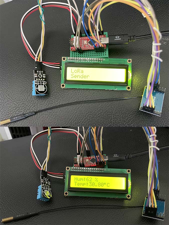
Figure 4: Author Prototype of LoRa Interfacing Transmitter Circuit
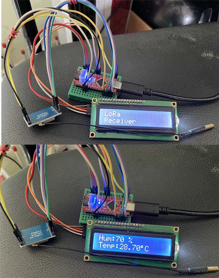
Figure 5: Author Prototype of LoRa Interfacing Receiver Circuit
it’s a really great project , I am working at the same project idea but i use the lora module to make the parent’s and child’s bracelet that able to communicate with each other wirelessly in order to make the parents always connected to the child so prevent them from kidnapping so i was wondering what is your opinion at this project and also i want to know how to add lora sx1278 to the proteus to be able to test the project before the physical implementation…Thanks for your time.