Power supply circuits are an essential component of any electronic device, providing the necessary voltage and current required for the smooth operation of the device. A well-designed power supply circuit ensures that the device receives a stable and regulated power supply, preventing damage due to voltage spikes or current surges.
In this article, we will discuss a ripple-free short circuit-protected variable power supply circuit design which is a highly efficient and reliable circuit that can provide precise and stable voltage and current outputs. The circuit is designed to maintain a constant voltage and current output, even when the load changes, making it ideal for use in various applications such as laboratory equipment, electronic test equipment, and battery charging circuits.
The power supply circuit we will discuss uses advanced technology to provide precise voltage and current regulation, while also being capable of delivering high power outputs. Furthermore, the circuit features a short-circuit protection mechanism, which protects the circuit and the connected device from damage in the event of a short circuit.
Overall, this article aims to provide a detailed overview of the short circuit, ripple-free variable voltage, and current power supply circuit, including its working principle, components, and design considerations. By the end of this article, you will have a thorough understanding of how the circuit works and how it can be implemented in various applications.
Circuit Description of Ripple-Free Short Circuit Protected Variable Power Supply Circuit Design
The logic of the circuit is very easy and even a common hobbyist can easily understand it, series pass transistor with a zener diode is used for regulation.
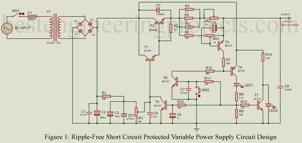
Here diodes D1 through D4 act as a bridge rectifier where capacitor C1 and C4 is used for smoothing. Finally, the zener diode ZD1 regulates the output voltage.
Glowing RED LED indicates the supply has tripped whereas GREEN LED indicates normal operating. Parallel connected resistor R3 through R5 conduct transistor T3 which further turns on the transistor T4. The voltage drop across resistor R9 due to the collector current of transistor T4 enables transistors T5 through T7 turns-on.
The output voltage from transistor T1 becomes zero when the collector voltage of transistor T5 is fed to its base. Transistor T6 is an active protection circuit because it holds the base current from transistor T4. In trip condition, GREEN LED remains off with the help of transistor T7.
Switch SW1 is used to reset, for again use. Capacitor C5 is used to prevent T3 from turning on at the surge current drawn by the load. Preset VR1 and VR2 is used as voltage and current controller respectively, where VR3 adjusts for maximum current.
Capacitor C3 zener diode prevents ripple from going into the base of transistor T1. The base capacitor at transistor T5 is used in order to avoid the false triggering of T5.
component list of Ripple-Free Short Circuit Protected Variable Power Supply Circuit Design
Resistors (all ¼-watt, ± 5% Carbon)
R1 = 390 Ω/1W
R2 = 22 Ω
R3 – R5 = 1.2 Ω/1W (Wired Wound)
R6 = 100 Ω
R7 = 30 KΩ
R8 = 2.7 KΩ
R9 = 330 Ω
R10, R11 = 10 KΩ
R12 = 39 KΩ
R13 = 27 KΩ
R14 = 3.3 KΩ
VR1 = 10 KΩ/1W LIN
VR2 = 10 Ω/1W Wire Wound
VR3 = 1 KΩ
Capacitors
C1 = 0.1 µF/100V
C2 = 2200 µF/50V
C3 = 100 µF/35V
C4 = 0.1 µF/50V
C5 = 4.7 µF/35V
C6 = 1 µF/10V
C7 = 0.01 µF
C8 = 0.22 µF/100V
Semiconductors
T1 = SL1L100
T2 = 2N3055
T3, T5, T6, T7 = BC147B
T4 = BC157B
D1 – D5 = 1N4003
ZD1 = 27V/1W
Miscellaneous
SW1 = ON/OFF switch
SW2 = PUSH–TO–ON switch
F1 = 200mA fuse
X1 = 230V 50Hz or 110V 60Hz primary 0–25V, 1.5A secondary.
I am a little confused. Are there missing junction dots around R3, R4 and R5, as well as on Zener ZD1 and the negative side of C5.
Thank you, Lew
We had updated the circuit.