The project “Arduino Based Temperature Controlled Fan” is extended version of previous post “Temperature Controlled Fan using Arduino”. Speed of fan depends upon the temperature it detect. This project has various features like:
Features of Arduino Based Temperature Controlled Fan
- Automatic fan speed control according to temperature.
- Temperature and speed are displayed over LCD.
- Control Circuit and Load circuit is isolated using opto-isolator 4N35 i.e. more protection.
- High Power drive circuit i.e. can drive high power high voltage DC fan.
- Maximum temperature indication using glowing LED.
Circuit Description of Arduino Based Temperature Controlled Fan
The circuit shown in figure 1 is designed arduino NANO, LM35 temperature sensor, opto-coupler 4N35, IGBT FGA25N120 and few other electronics components as shown in figure below. For proper description we had divided the complete circuit into various small section.

Arduino and LM35 Interfacing
LM35 is a temperature sensor which sense temperature and generate voltage according to temperature According to datasheet of LM35 it produces 10mV per degree change in temperature. Arduino read this value using its internal analog to digital converter (ADC). Arduino have inbuilt 10-bit ADC i.e. 1024 steps. By default, arduino can map 5V input voltage into 1024 steps. Therefore, the resolution of arduino is 5/1024 = 4.88×10⁻³V = 4.88mV. By default, Arduino can detect 4.88mV change. From datasheet of LM35, 10mV change in per degree Celsius. So, if we use default arduino reference then it give accuracy of about 0.50C.
Arduino and LCD Interfacing
LCD is connected to arduino in higher order data mode i.e. only higher order data pin D4 to D7 of LCD is connected to arduino nano for data displaying. Enable and Set/Reset pin is connected to arduino as shown in circuit diagram. Pin 1, Pin 5 and pin 16 of arduino is connected to ground where Pin 2 is connected to power supply. Pin 15 of LCD (LED+) is connected to +5V through a current limiting resistor. At Pin 3 of LCD we have to supply voltage between Vcc and Vss, so a variable resistor is connected as shown in circuit diagram.
Check out the video on “Tutorial on Interfacing 16×2 LCD to Arduino”.
Switching Circuit
In previous project “Temperature Controlled Fan using Arduino” we had used a transistor in order to drive DC fan. As there are some limitation of using transistor like low output current, low output voltage etc. In order to overcome this problem, we are using IGBT (Isolated Gate Bipolar Transistor). According to data sheet it can handle 600V @ 25A which is huge.
Arduino alone cannot drive the IGBT because it requires more voltage then the arduino output voltage. So, in order drive the IGBT an opto-coupler 4N35 is used. This opto-isolator also isolate control circuit and load circuit. PWM output of arduino drive opto-isolator 4N35 which further drive IGBT.
Checkout the previous article “Interfacing Optocoupler with Arduino”.
Gate of IGBT is connected to pin 4 of opto-coupler. One resistor is connected between gate of TGBT and ground of power supply in order to avoid false triggering. DC fan is connected between power supply and collector of IGBT as shown in circuit diagram. One fly back diode is connected across DC fan in order protect the circuit from transient volt produced in inductor. Power supply is used according to power rating of DC fan.
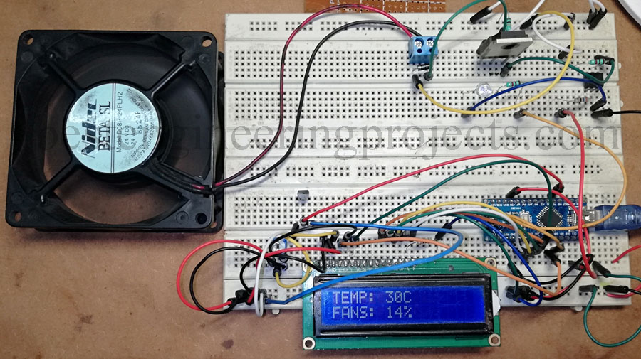
Figure: Author Prototype Arduino Based Temperature Controlled Fan
Working of the Circuit Arduino Based Temperature Controlled Fan
Temperature sensor detect the temperature and generate voltage according to temperature it senses. Arduino nano compare output voltage of temperature sensor and operate the fan. As we are using PWM pin, the speed of fan is variable according to temperature. According to the software code fan start to rotate at 300C and at 600C speed of fan become 100%. LCD shows the value of temperature and fan speed. LED1 indicate the temperature status i.e. glowing LED indicate temperature is maximum.
Software Code:
Software code of Arduino Based Temperature Controlled Fan is written in arduino programming language and compiled using arduino IDE. Program is simple and straight forward, it basically check the temperature and compare between two temperature range (250C to 600C). Speed of fan depends upon temperature which we map between 32 and 255 and fan speed is display which is map between 0 to 100 as shown in below.
|
1 2 |
fanSpeed =map(temp, tempMin, tempMax, 32, 255);//Speed of Fan at PWM output fanLCD = map(temp, tempMin, tempMax, 0, 100); // speed of fan to display on LCD100 |
Now, let’s see the complete code
|
1 2 3 4 5 6 7 8 9 10 11 12 13 14 15 16 17 18 19 20 21 22 23 24 25 26 27 28 29 30 31 32 33 34 35 36 37 38 39 40 41 42 43 44 45 46 47 48 49 50 51 52 53 54 55 56 57 |
#include <LiquidCrystal.h> LiquidCrystal lcd(7,6,5,4,3,2); int tempPin = A1; // the output pin of LM35 int fan = 11; // the pin where fan is int led = 8; // led pin int vout,temp; int tempMin = 25; // the temperature to start the fan 0% int tempMax = 60; // the maximum temperature when fan is at 100% int fanSpeed; int fanLCD; void setup() { pinMode(fan, OUTPUT); pinMode(led, OUTPUT); pinMode(tempPin, INPUT); lcd.begin(16,2); Serial.begin(9600); } void loop() { vout = analogRead(tempPin); temp = vout * 0.48828125; Serial.print( temp ); if(temp < tempMin) // if temp is lower than minimum temp { fanSpeed = 0; // fan is not spinning analogWrite(fan, fanSpeed); fanLCD=0; digitalWrite(fan, LOW); } if((temp >= tempMin) && (temp <= tempMax)) // if temperature is higher than minimum temp { fanSpeed =map(temp, tempMin, tempMax, 32, 255); fanLCD = map(temp, tempMin, tempMax, 0, 100); // speed of fan to display on LCD100 analogWrite(fan, fanSpeed); // spin the fan at the fanSpeed speed } if(temp > tempMax) // if temp is higher than tempMax { digitalWrite(led, HIGH); // turn on led } else // else turn of led { digitalWrite(led, LOW); } lcd.print("TEMP: "); lcd.print(temp); // display the temperature lcd.print("C "); lcd.setCursor(0,1); // move cursor to next line lcd.print("FANS: "); lcd.print(fanLCD); // display the fan speed lcd.print("%"); delay(1000); lcd.clear(); } |