Imagine that you are in the middle of an important project, and suddenly your batteries run out. That’s frustrating, right? Well, here’s the good news-you can build your very own battery charger circuitry that’s intelligent, efficient, and automatic. Using an LM317 voltage regulator and a relay, this circuit not only charges your batteries but also stops charging once they’re full. Think of it as a responsible babysitter for your batteries! This guide walks you through a simple battery charger design that can safely charge four series-connected AA cells (1.5V each).…
Search Results for: battery charger
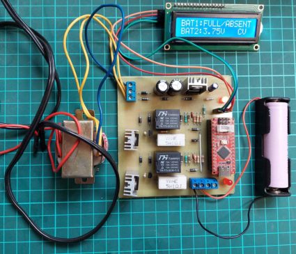
Arduino LiFePO4 Battery Charger Circuit
Amongst the rechargeable batteries available on the market, Lithium Iron Phosphate battery (LiFePO4 battery) or LFP battery (Lithium Ferro Phosphate) is widely used due to the various benefits offered, compared to other batteries. Longer life span, highly safe, lightweight, improved discharge, and charge efficiency are some of the advantages provided by the LiFePO4 batteries. In the market, you will find different types of LiFePO4 battery chargers that may or may not fulfill your requirements, and you may find them expensive. Previously, we had already discussed a DIY LiFePO4 battery charger…
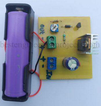
Lithium Ion Battery Charger Circuit using LM317
A Lithium-Ion Battery Charger Circuit using LM317 charges the battery in two different modes: constant current mode and constant voltage mode. Lithium polymer or lithium-ion batteries are very prone to overcharging or charging with high voltage or high current. Thus, when designing the charger circuit for Li-ion or Li-Po, we must consider a few things, such as charging voltage and current. The circuit posted here is designed using one of the famous variable voltage regulators, IC LM317. This circuit charges the battery in two modes, i.e., constant current and voltage.…
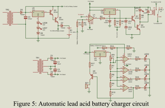
Automatic Lead Acid Battery Charger Circuit
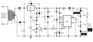
An automatic lead acid battery charger circuit is designed to charge 12V, and 40Ah in different charging modes i.e. boost mode and float mode. This circuit can be used to charge large-capacity inverter batteries by replacing transformers and power transistors with higher ratings. To know the condition of the battery and charger unit, this circuit was incorporated with an audiovisual indication unit. Before going to the circuit description and working let’s see its salient features: Features of Automatic Lead Acid Battery Charger Circuit Automatic charger the battery and maintain the…
LiFePO4 Battery Charger Circuit
Lithium Iron Phosphate LiFePO4 or Li-Fe battery is the latest generation of Li-ion battery and is popular among electronics hobbyists because of its features like high discharge current rate, safety and it is the least toxic of all battery types. Also, these batteries are safer because of the chemistry involved to make them. It contains a very stable composition of phosphate as a result longer life span of the battery can be achieved. However, the latest generation Li batteries are non-inflammable and are capable of bearing extreme conditions. In this…
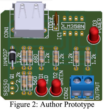
12V Lead Acid Battery Charger Circuit
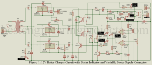
There are lots of 12V Lead Acid Battery Charger Circuit available over the internet but does not include a battery status indicator. If you wish to know the status of the battery like dead, charged, or charging you need an extra circuit. In order to solve these problems, we combined three different circuits and hence do three different dedicated jobs like charging the battery, indicating the status of the battery, and also have a dedicated port for variable power supply connector of bench power supply in case you need. This…
Arduino Controlled 12V battery charger circuit
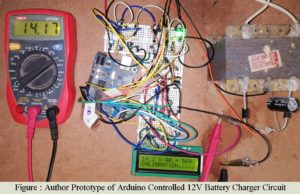
Arduino is an open-source that is designed for artists or for those who do not have an electronic background. Here, in this article, we are going to show you the method of making a battery charger circuit controlled using an Arduino uno board. The project Arduino Controlled 12V battery charger circuit is an advanced version of the previous posted project “12V, 7Ah Smart Battery Charger with PCB Diagram”. This charger also has the features of bulk stage charging and float stage charging as in the previous circuit. Silent features of…
12v, 7Ah Smart Battery Charger with PCB Diagram
Here is a 12V, 7Ah smart battery charger circuit which is also referred to as a smart charger uses three-stage of charging i.e. bulk stage, absorption stage, and float stage. Normal battery charger technology uses single-stage battery charging technology i.e. only charge the battery up to the maximum charging voltage preset by the charging circuit. Now here is a 12V, 7Ah smart battery charging circuit which is also referred to as a smart charger uses three-stage of charging i.e. bulk stage, absorption stage, and float stage. You may also like Arduino…
12 V Battery Charger with overcharge and deep-discharge protecting
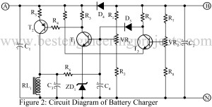
Introduction of 12 V Battery Charger with overcharge and deep-discharge protecting Mostly in broad projects, we have seen lead-acid storage cells are often used as a backup source of electrical energy during periods of supply line failure so that the system operates efficiently. In case of mains supply failure, the energy (i.e. electrical) stored in the cell is used and later when the mains supply is available, the energy in the cell is restored from the mains through a device named a charger. The cell undergoes chemical processes during the charging…
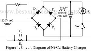
Ni-Cd Battery Charger
These days many of electrical appliances (watch, RC car, radio etc) use Ni-Cd battery. Here is a simple circuit of Ni-Cd battery charger in the series of easy electronics projects. Circuit Description and working principle of Ni-Cd Battery Charger Basically Circuit of Ni-Cd battery charger is rectifier. The input from AC mains is directly given to the circuit through resistors R1 and R2, where resistor R1 is used to limit the surge current and resistor R2 with capacitor C1 is used to limit the leakage charge current. The output from…

