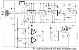
Introduction | Load Protector Circuit and Remote Switching Have you ever noticed the number of devices used at your house to serve your purpose? There are many. These devices require a specified rate of power to operate. Maximum variations in voltage/ power and load can destroy most of the devices like inverters and UPS systems since it can cause excessive heating of the output transformer windings and the active driving device and thereby damage them. And, some domestic appliances also need to be protected against under/over-voltage. This particular circuit serves the…
Search Results for: battery charger
Advance Mini UPS Circuit
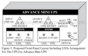
Mobile phones and small electronic gadgets are powered by AC mains using an AC adapter. In the event of mains failure, a low-capacity UPS will do the job satisfactorily. Here we design a simple, efficient, economical, and easy-to-construct UPS for mobile phone or telephone sets. The project advanced mini-UPS circuit can also be used for high power by changing a transformer with a high current rating so this circuit can be used as power backup for laptops also. We have already posted 350VA Offline UPS Circuit. Block Diagram of Advance…
Advance Emergency Light Circuit
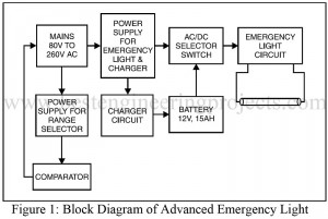
Many types of emergency light circuits are already available in the web world. Now, here is a unique circuit that glows a fluorescent tube at a voltage as low as 80 volts. This unique circuit Advance Emergency Light Circuit operates at a 12V battery and also charges the battery up to 12V, 15AH at a constant rate. Block Diagram of Advance Emergency Light Circuit The block diagram of the advanced emergency light circuit with charger unit is shown in figure 1. It consists of a power supply for emergency light,…
Crystal controlled inverter | Verified Inverter Circuit
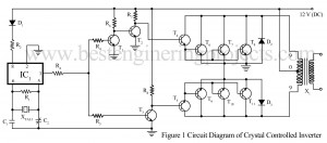
Many Inverter Circuits have already been posted on many other websites. The inverter circuit “Crystal Controlled Inverter” presented here provides a stable output frequency even when there is a change in the DC voltage applied to the inverter. This stable output of the Crystal control Inverter is obtained from the 3.2786 MHZ crystal (XTAL1). You can also make your 3000W inverter using a microcontroller. Circuit Description of Crystal Controlled Inverter. The Inverter circuit “Crystal Controlled Inverter” is built around popular flip flop IC MM 5369 (IC1) followed by a few…


