Many types of emergency light circuits are already available in the web world. Now, here is a unique circuit that glows a fluorescent tube at a voltage as low as 80 volts. This unique circuit Advance Emergency Light Circuit operates at a 12V battery and also charges the battery up to 12V, 15AH at a constant rate.
Block Diagram of Advance Emergency Light Circuit
The block diagram of the advanced emergency light circuit with charger unit is shown in figure 1. It consists of a power supply for emergency light, charger circuit, AC/DC selector switch, power supply for range selector, and comparator. This emergency light circuit works off either AC mains or DC supply.

Description of Advance Emergency Light Circuit
The input AC voltage is stepped down to 24V by transformer X2 and rectified using a rectifier circuit comprises of diodes D7 through D10. The pulsating DC voltage from the rectifier is filtered by capacitor C2 and is given to non-inverting input (pin 3) of op-amp through resistor R1 and preset VR1. The reference voltage from the voltage regulator IC (IC4) and voltage divider circuit (comprises resistor R2 and R3) is given to inverting input of IC2 (pin 2).
At input mains when AC volt becomes greater than 115V, the output of the voltage comparator (IC2) goes high which further energizes the relay RL1. As a result, the 230V terminal on the primary of transformer X1 is connected to the AC mains. Transformer X1 step-down 230V to 24V secondary output, if the input mains voltage is less than 115V, the low output of comparator re-energizes relay RL1. Therefore transformer 115V trapping of primary transformer X1 gets connected to the AC mains supply. At this time transformer X1 step-down the input voltage of 115V to 24V, this is always constant.
The stepped-down voltage from the transformer is rectified by using a full-wave bridge rectifier comprising diodes D1 through D4. Capacitor C1 filters the pulsating DC voltage is further given to the emitter of PNP transistor T1 and input of the voltage regulator IC1 through resistor R5 as shown in the circuit diagram. The regulator IC1 delivers a current of about 500mA at 12V which is insufficient for working the circuit advance emergency light. Therefore transistor T1 provides a bypass path for a current above 300mA.
As a voltage regulator, IC has the facility like internal over-voltage protection, which automatically turns off when the input voltage is more than 35V i.e. when the mains voltage reaches about 260V in this circuit. Therefore the input voltage range of the regulator is 80V to 260V and the output is always constant at 12V as mentioned above.
Relay RL2 is used to select the source as the output voltage of regulator IC (IC1) when AC power is present which is indicated by glowing LED1. Relay RL3 disconnects the supply when the circuit is working with regulated output which is indicated by glowing LED2. Switch SW1 to the off position and charge the battery when the advanced emergency light circuit is not in use.
The charger circuit is built around an adjustable voltage regulator IC (IC3). The output from pin 2 of IC3 is given to the positive terminal through current limiting resistor R8. Diode D5 stops the reverse voltage from the battery and also prevents relay RL1 to energize from the battery. The output voltage of the charger unit is adjusted with the help of a preset VR3.
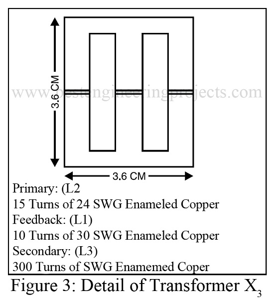
The circuit of emergency light is an inverter circuit and is built around transistor T2, resistor R10, capacitor C5, and ferrite transformer X3. It operates at a very high frequency (above 20 kHz), which enables transformer X3 to step up the primary voltage from a 12V source to around 700V erratic pulses (peak-to-peak) in the secondary (due to ionization inside the fluorescent tube). Here we’ve used a ferrite core transformer so that core losses are low.
Winding details of transformer X3 are given in Fig. 3.
Check out other power supply and inverter circuits posted on besengineeringprojeccts.com
- Offline UPS Circuit
- 3000W Inverter with Inbuilt Charger using AT89C2051
- Crystal controlled inverter | Verified Inverter Circuit
- Advance Mini UPS
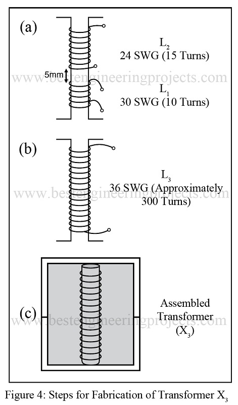
The steps for winding transformer X3 are as follows:
- Take the bobbin of the ferrite core transformer and wind coils L1 and L2 side by side as shown in Fig. 4(a).
- Cover the coils with a paper insulator and wind coil L3 over it. After 150 turns are completed, cover this layer (Fig. 4(b)) with a paper insulator.
- Cover the final secondary winding having 300 turns with the paper insulator and insert the ferrite core in the bobbin as shown in Fig. 4(c). Finally, fix the core using insulation tape.
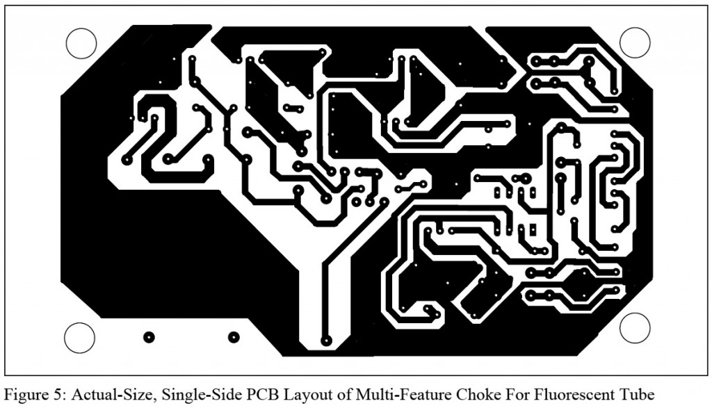
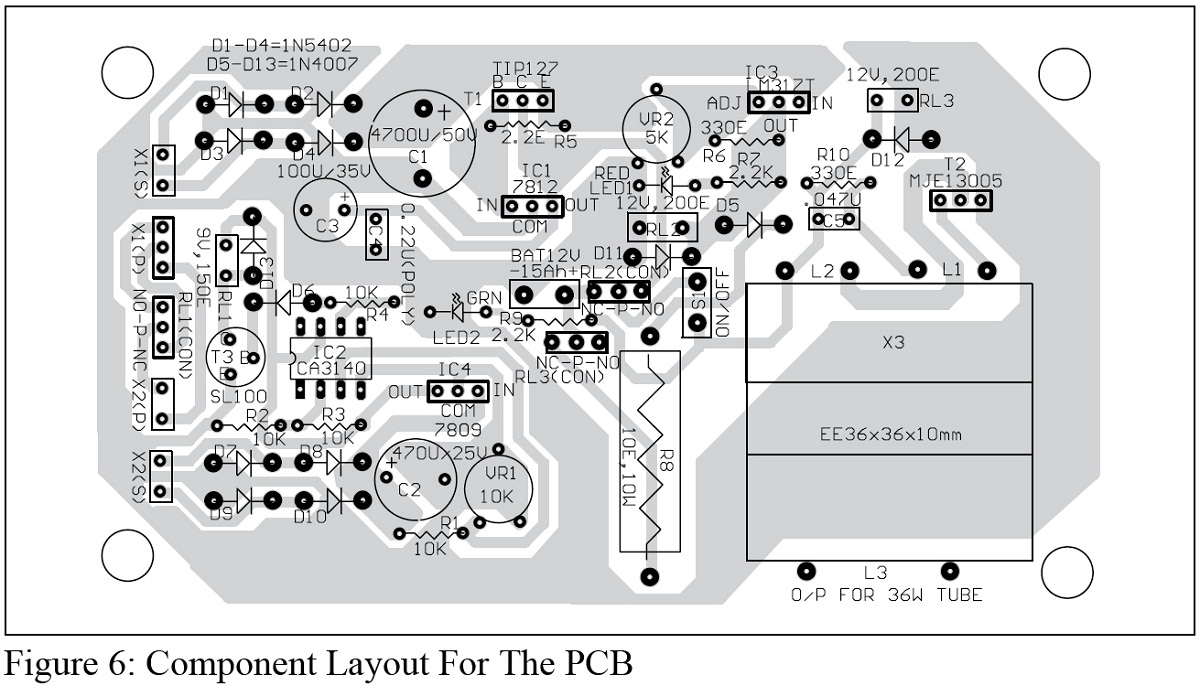
PCB Design:- The actual-size, solder-side PCB for the advanced emergency light is shown in Fig. 5, and it’s component layout in Fig. 6.
PARTS LIST OF ADVANCE EMERGENCY LIGHT CIRCUIT
| Resistor (all ¼-watt, ± 5% Carbon) |
| R1 – R4 = 10 KΩ
R5 = 2.2 Ω, 0.5W R6, R10 = 330 Ω R7, R9 = 2.2 KΩ R8 = 10 Ω, 10W VR1 = 10 KΩ pot. VR2 = 5 KΩ pot |
| Capacitors |
| C1 = 4700 µF, 50V (Electrolytic Capacitor)
C2 = 470 µF, 50V (Electrolytic Capacitor) C3 = 100 µF, 35V (Electrolytic Capacitor) C4 = 0.22 µF, 100V (polyester Capacitor) C5 = 0.047 µF, 100 µF (polyester Capacitor) |
| Semiconductors |
| IC1 = LM7812 (12V, Series voltage regulator IC)
IC2 = CA3140A (Operational Amplifier IC) IC3 = LM317T (Variable Voltage Regulator IC) IC4 = LM7809 (9V, Series voltage regulator IC) T1 = TIP127 (PNP Darlington Bipolar Power Transistor) T2 = MJE13005 (NPN Bipolar Junction Transistor) T3 = SL100 (general purpose, medium power NPN transistor) D1 – D4 = 1N5402 (General Purpose Rectifier Diode) D5 – D13 = 1N4007 (General Purpose Rectifier Diode) LED1 = Red LED, 5mm LED2 = Green LED, 5mm |
| Miscellaneous |
| X1 = 0V-115V-230V AC primary to 0-24V, 3A Secondary
X2 = 0V-230V AC primary to 0-24V, 500mA Secondary X3 = 12V, 40W inverter transformer RL1 = 9V, 150 Ω,1 C/O relay RL2, RL3 = 12V, 200 Ω, 1 C/O relay |


