For a 3-phase induction motor, all three phases of the supply must be present. If any of the phases is missing, or a fuse is blown, the motor will continue to run with two phases only. But in that case, it will draw a very large current, and it may burn unless switched off immediately. To solve this problem the project “Single Phase Preventer with Under/Over Voltage Cutout” is posted here.
For the protection of a three-phase induction motor, various types of starters are utilized. But the problem with Starters is, it can only protect induction motors from overload; they cannot prevent motor burn-out under the above conditions. This “Single Phase Preventer with Under/Over Voltage Cutout” circuit protects the motor by stopping it automatically under such conditions. We already control 3-phase machinery using Single Phase Preventer Circuit, this time we come with a little different concept. You can also check 3-Phase Induction Motor Starter.
Circuit Description of Single Phase Preventer with Under/Over Voltage Cutout
X1 is a step-down transformer, the primary of which is connected to 440 volts AC supply. its secondary is connected to a bridge rectifier comprising diodes D1 to D4, and the voltage is then smoothed by capacitor C1.
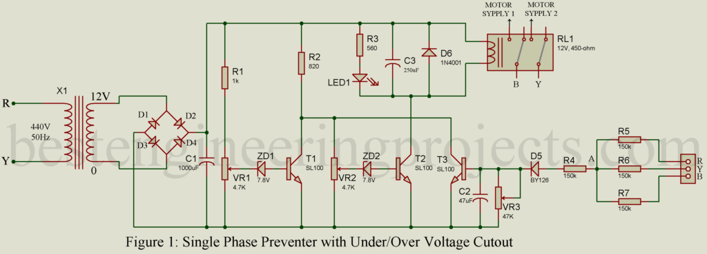
Next to a power supply is a cut-off relay circuit. When the supply voltage is within limits, transistor T2 is conducting, and T1 is in a cut-off state. Hence relay stays energized. LED is connected to the circuit to indicate where the relay is energized. Resistor R3 is a current limiting resistor and is connected to a series of LEDs to protect it from burn-out.
When the voltage is too low, Zener diode ZD2 will not break down, and transistor T2 will not conduct, causing the relay RL1 to de-energize. Variable resistor VR1 is used to adjust. When there is a high voltage, Zener diode ZD1 breaks down and let transistor T1 conducts, and the relay again remains de-energized.
Then comes the single-phase preventer circuit with under/over voltage cutout. The three-phase supply consists of three equal voltages with phase differences of 1200. Thus, the sum of three-phase voltage is zero volts. The three phases R, Y, and B are connected to a neutral line, which in turn is connected to the ground of the circuit. When all three phases are present, the voltage at point A is zero. So, the voltage at the base of T3 is zero.
If any of the three phases is missing, or if a fuse gets blown, a voltage equal to half the line voltage appears at point A. this voltage is fed to the half-wave rectifier (diode D5). It is varied by potentiometer VR3, which when properly adjusted turns transistor T3 on, but cuts off T2. This de-energizes the relay again and the motor is prevented from burning.
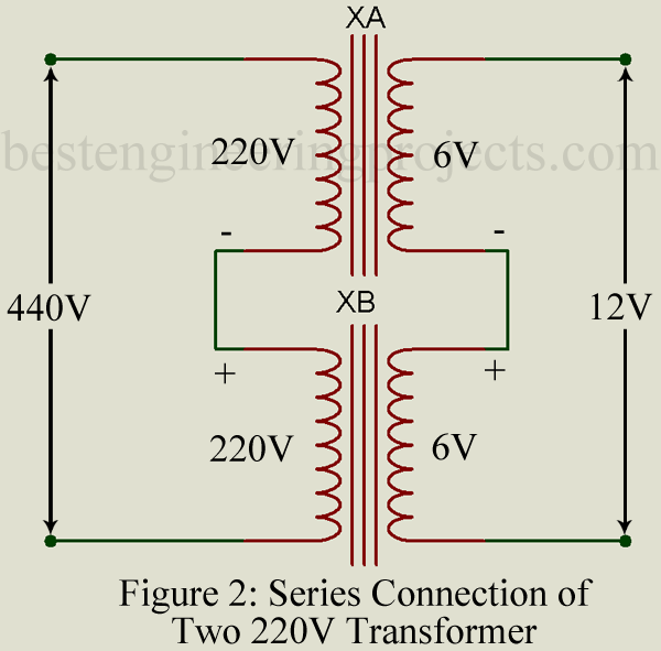
Note: You can replace 440V primary transformer with to 12V secondary transformer with two 220V primaries to 6V secondary transformer must be connected in series as shown in the figure below. Specification of transformer must be same for two i.e. 220V to 6V @ 500mA transformer. One end of the primary side of transformer XA and XB is connected to a 440V main power supply while the remaining terminal of transformer XA and XB are connected as shown in the circuit below. Similarly. do the same thing for the secondary side i.e. GND terminal of transformer XA is connected to the 6V terminal of the transformer. You will get 12V from the 6V terminal of transformer XA and 0V from the GND terminal of XB.
PARTS LIST OF SINGLE PHASE PREVENTER WITH UNDER/OVER VOLTAGE CUTOUT
| Resistors (all ¼-watt, ± 5% Carbon else Specified) |
| R1 = 1 KΩ
R2 = 820 Ω R3 = 560 Ω R4 – R7 = 150 KΩ, 0.5W VR1, VR2 = 4.7 KΩ (POT.) VR3 = 47 KΩ (POT.) |
| Capacitors |
| C1 = 1000 µF/25V (Electrolytic Capacitor)
C2 = 47 µF/16V (Electrolytic Capacitor) C3 = 250 µF/16V (Electrolytic Capacitor) |
| Semiconductors |
| D1 – D4 = BY127 (Silicon Low power Rectifier Diode)
D5 = BY126 (Silicon Low Power Rectifier Diode) D6 = 1N4001 (1A General Purpose Rectifier Diode) ZD1, ZD2 = 7.8V, 1W Zener Diode T1 – T3 = SL100 (General Purpose Medium Power NPN Transistor) |
| Miscellaneous |
| X1 = 440V Primary to 12V, 500mA Secondary Transformer
RL1 = 12V, 450 Ω, Double Pole Double Throw (DPDT) Relay |