If we have been familiar with machinery, we all know how important it is to follow safety measures to mitigate injuries and accidents. A single phasing preventer circuit is one of the solutions we can look forward to. The phrase ‘preventer circuit’ itself portrays it. The single-phase preventer circuit is also a high low and unbalanced-supply voltage cut-off relay. To ensure complete safety for 3-phase machinery, the preventer circuit has been known to be handy.
Generally, an induction motor burns out due to excessive voltage during an off-hour, a very low voltage during peak hours along with an unequal phase voltage, and a single phasing (missing of one phase completely from the 3-phase supply). It is, therefore, considered essential to install a single phasing preventer in addition to the starter. The starter happens to provide overload protection only and therefore it cannot prevent the motor from burning out under the aforementioned conditions of the supply voltage. But, under such conditions, this preventer circuit helps to protect the motor by bringing it to a halt automatically. You might as well check out another project similar to this one, on single phasing preventer “Single Phase Preventer with under overvoltage cutout“.
Description and Working of Single Phasing Preventer Circuit
For simplicity, this Single Phasing Preventer Circuit can be divided into three parts, viz, power supply, unbalanced sensor, and cut-off relay.

As shown in figure 1, the primary transformer X1 is connected to a 400V supply line. The induced 12V AC in the transformer’s secondary is rectified by the bridge rectifier comprising of diodes: D1 to D4 and the smoothing capacitor C1. The capacitor C1 is deliberately chosen low in value for obtaining poorly regulated rectified voltage to ‘sense’ the variation in the line voltage from the specified voltage level.
Unbalance Sensor | Single Phasing Preventer Circuit
As shown in figure 2, the unbalanced supply sensing circuit comprises an RC network, a bridge rectifier, and a transistor T3. The three-phase of the supply lines R, Y, and B are connected to the corresponding terminals of the RC network. By this design, the terminal ‘P’ and ‘Q’ stay at the same potential when a balanced supply (balanced 3-phase supply consists of three equal voltages with a phase difference of 1200) is fed to the RC network. By any means, if any one of the phases is absent, or the voltages happen to be unequal, or even if the phase sequence is reversed, there exists a certain potential difference between terminals ‘P’ and ‘Q’.

The potential difference is fed to the bridge rectifier through a preset. As a result, the bridge rectifier conducts forward bias transistor T3. The transistor, in turn, actuates the cut-off relay circuit to disconnect the supply to the motor. The preset VR3 can be adjusted against the unbalanced supply. In other words, if 5% or 10% unbalanced supply is admissible, VR3 can be adjusted so as not to actuate the circuit when the unbalanced supply is less than 5% or 10%.
Cut-off Relay Circuit | Single Phasing Preventer Circuit
The cut-off relay circuit is a unique bistable multivibrator. As shown in figure 3, it forms an unconventional multivibrator. In this circuit, only one transistor conducts at a time.
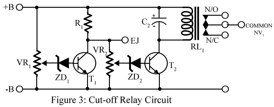
When the supply is within limits, transistor T2 alone conducts and transistor T1 stays in its non-conducting state. Hence, the relay RL1 stays energized. The relay contacts are connected in series with the no-volt coil of the starter.
If the line voltage falls very low, the Zener diode Z2 will not break down (under good supply conditions Z2 is adjusted by preset VR2 to its breakdown state). This, in turn, removes all forward bias from the transistor T2. Hence, the transistor T2 does not conduct and the relay is de-energized and stops the motor by breaking the no-volt circuit of the starter.
If the voltage rises excessively, the zener diode (which is adjusted by preset so as not to conduct when the line voltage is within the specified limits) will break down and drive the transistor T1. Consequently, the motor stops.
Testing of Single Phasing Preventer Circuit
Testing can be carried out by the techniques used in repairing transistorized circuits. The following steps are recommended:
- Measure the HT supply: If absent, search for an open circuit in the primary or secondary winding of X1, or perhaps capacitor C1 is short-circuited or diodes D1 to D4 are faulty.
- If proper HT is present, but the relay is inoperative, try up and down adjustment of VR1 and VR2. If there is no change, search for the emitter-to-collector short circuit of the transistors T1 and T3, faulty Zener diodes and the transistor T2, or open circuit of VR2, R1, or RL1.
- If the relay is in an inoperative state, adjust VR1 and VR2 such that the relay gets de-energized at certain points. If the relay stays at the same energized position, search for short in T2 or ZD2.
- Disconnect one phase from the RC network and observe the relay’s state; it should be de-energized. If not, suspect faulty components of the RC network, the bridge rectifier, and the transistor T3.
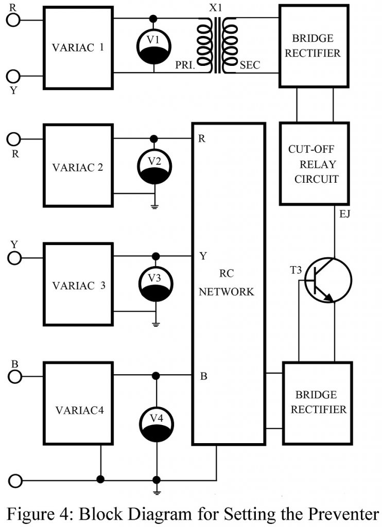
The setting of Single Phasing Preventer Circuit
As shown in figure 4, the setting is carried out by four variable auto-transformers and four AC voltmeters of the 500V range. The following are the setting operations:
-
- Vary all the variable auto-transformers to read 415V in voltmeter V1 and 220V in V2, V3, and V4. Now, set VR1, VR2, and VR3 such that the relay stays in its energized state.
- Decrease the voltage across X1 by variable auto-transformer 1 to 360V and VR2 to de-energize the relay.
- Increase the voltage to 470V and set VR1 to pull down the relay.
- Set the voltage to 415V across X1 and turn the autotransformers 2, 3, and 4 to read the voltage of 250, 220, and 190 volts in V2, V3, and V4 respectively. Now, set VR3 to pulldown the relay.
Installation of Single Phasing Preventer Circuit
This installation of the preventer circuit is shown in figure 5. The figure indicates:
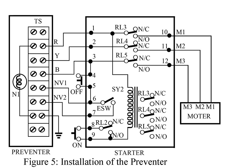
- R, Y, and B are three-phase of the supply
- 1, 2, and 3 are starter’s R, Y, and B terminals.
- RL2, RL3, RL4, RL5 are no-volt relay coil contacts
- M1, M2, and M3 are motor’s R, Y, and B terminals
- NV1 and NV2 are preventer’s relay contacts
- N1 is Neon Lamp
- ESW is an emergency switch, that provides us to operate the motor even under serve conditions of supply, at our own risk.
- TS is a six-terminal, terminal stay connector.
PARTS LIST OF SINGLE PHASING PREVENTER CIRCUIT
| Resistor (all ¼-watt, ± 5% Carbon) |
| R1 = 470 Ω, 1W
R2 – R7 = 120 KΩ, 1/2W VR1, VR2 = 5 K KΩ VR3 = 220 KΩ |
| Capacitors |
| C1 = 470 µF, 16V
C2 = 200 µF, 16V C3 = 330 µF, 50V C4, C5 = 0.01 µF, 500V |
| Semiconductors |
| D1 – D8 = 1N4007
T1, T2 = CIL333 ZD1, ZD2 = BZ148 (10%) |
| Miscellaneous |
| X1 = 440V ac to 12V, 500mA step down transformer
RL1 = 12V, 450Ω Relay |
(This article was originally posted on December 18, 2016, and updated on May 16, 2021)