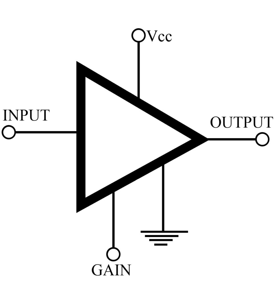
In this article we will see details like key parameters , applications and parts number of Class B, Class C and Class AB amplifier IC.
Description of Class B Amplifier:
In this type of amplifier, the quiescent (Q) point is set exactly at the cutoff of the IC curve, resulting in amplification of only one half-cycle of the input sinewave. Class B amplifiers are invariably connected back to back in push-pull circuits. In this arrangement one amplifier is operating during the positive cycle of the sinewave and is cut off while the other amplifier is operating on the negative part of the sinewave. Widely used as audio amplifiers, servo amplifiers, and in similar applications where a linear sinewave output is essential, Class B amplifiers feature excellent efficiency and good second and third harmonic distortion characteristics. Some distortion occurs near the zero-crossover point because of the slight nonlinearity of the IC curve at the point. Where very good linearity is essential, Class AB amplifiers are used in push-pull circuits.
Check out derivation and analysis of Class B Push-Pull Amplifier
Applications:
Class B amplifiers are extensively used for audio work in portable players, as stereo amplifiers and in highly-fidelity radio receivers.
Representative Part Number: Fairchild TBA 810S.
You may also like audio amplifier using TBA810 : 7W audio amplifier using TDA810
Description of Class C Amplifier:
In the class C amplifier, the quiescent (Q) point is located at twice the cutoff on the IC curve. Only one-half of a sinewave half-cycle is actually amplified at the output. Class C amplifiers are usually used in RF oscillators and, in some instance, in RF transmitters. In these applications the flywheel effects of the resonant circuit supply the other half of the cycle. High efficiency is the key feature for the Class C amplifier in properly designed and aligned RF circuits.
Key Parameters of class C amplifier
- Gain: In most applications a voltage gain of 20 is adequate.
- Frequency: For application as RF oscillator or transmitter output amplifier, the frequency limit of the device should be at least 10% above the expected resonant frequency.
- Power output: Depending on the actual frequency, power output may vary but is a key design criterion.
- Power Dissipation: Class C amplifiers usually operate near the limits of their power dissipation specifications, and the thermal characteristics of the mechanical mounting arrangement may become critical.
Applications:
Class C amplifiers are usually found in oscillators at frequencies above 100 kHz. Linear sinewave output and freedom from harmonics are usually not important in such applications as walkie-talkies or remote-control transmitters. Special high-frequency ICs are used in Class C oscillators, reaching into the microwave band.
Comments
Listed here in order to present a complete picture of amplifiers, Class C amplifiers, as such, are not widely used in IC applications.
Description of Class AB Amplifier IC:
In this type of amplifiers, the quiescent (Q) point is set below the center of the linear portion of the IC-curve. As a result, one-half of the output will be the linear reproduction of one-half of the input, but the second half of the output signal will be partly suppressed. There are two versions- the Class AB1 and Class AB2. In the Class AB2, the Q point is fairly close to the cutoff point; in the Class AB1, the Q point is about 20% or 30% above the cutoff point. Both versions are used in push-pull circuits, and by, arranging them back to back, the cross over distortion can be minimized. The AB2 version is somewhat more efficient than the AB1 but not as good as the Class B. Class AB1 and AB2 amplifiers are used widely as push-pull amplifiers to drive speakers to servo motor, applications where linear sinewave amplification with moderated amounts of power is required.
Key Parameters
Key parameters of Class AB are same as Class A and Power Amplifier.
Representative Part Number: Sprague ULN-3705M.
