One of the most common projects made in electronics is burglar alarm or security alarm. If your search over the internet there are dozen of burglar or security alarms but the problem with this circuit is, it does not have a self-resetting option i.e. continuously sounds till someone switches off the system. Thus, in order to solve this type of problem (self-resetting) we have come with the project Self Resetting LDR Alarm using Timer IC 555.
This circuit detects the interruption of light and produces sound for a definite interval of time. By using the circuit configuration and electronics component shown in figure 1, the time interval is of 10 seconds which can be adjusted (increased or decreased) by adjusting the value of resistor and capacitor used in this circuit.
Circuit Description of Self Resetting Alarm using Timer IC 555
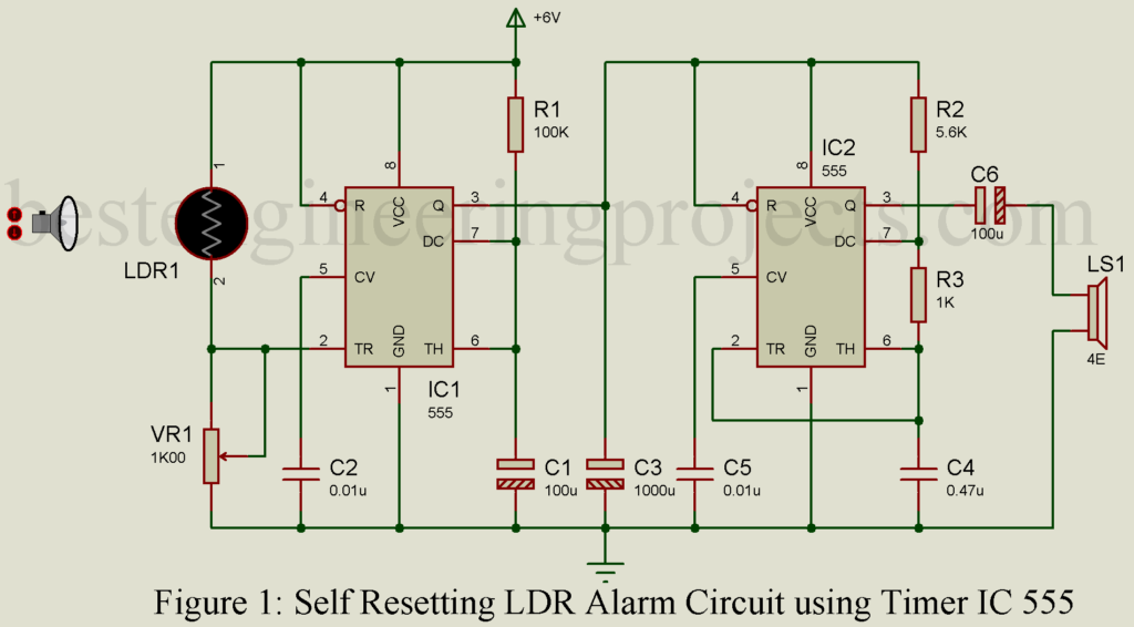
The circuit diagram of Self Resetting Alarm using Timer IC 555 is shown in figure 1. The construction of this project is very simple and is built using the most commonly used IC in the history of electronics i.e. Timer IC 555.
The circuit uses two ICs, namely 555 timers. The first one is used in monostable mode while the second IC is used as an audio oscillator, i.e. in astable mode. The monostable mode is also called timer mode because it produces one-shot output for a definite interval of time i.e. produce output high for a fixed interval of time. The astable mode is also called frequency oscillator mode because it produces frequency.
Check out other interesting projects using LDR posted in bestengineeringprojects.com
- Photoelectric switch using ne555
- Light Sensor Switch Circuit using LDR and 741 IC
- Automatic Light Operated Switch using LDR and IC741
- Automatic Fence Lighting with Alarm
- IC 555 Based Automatic evening lamp
Working of Self Resetting Alarm using Timer IC 555
When the beam of light is focused on LDR, its resistance remains low and the trigger terminal (pin 2) of IC1 (IC 555) is held at positive potential and its output is zero. Whenever the beam is interrupted, the resistance of LDR goes high. During that moment a negative pulse is applied to the trigger terminal and IC1 (IC 555) performs a 10-second monostable operation. The output of IC1 gets applied to the audio oscillator consisting of IC2 which gives an alarm for ten to eleven seconds.
Calculation of time and frequency
The time period of the operation can be changed by varying the values of resistor R1 and capacitor C1. The time period of operation is


The Frequency of audio oscillator IC2 can be changed by varying the value of R3 and C4. The frequency of oscillation is given by


Timer IC 555 (IC2) oscillates at the frequency of about 400 Hz.
The sensitivity of the alarm can be adjusted by setting 100K potentiometer VR1.
PCB Diagram:
PCB diagram of Self Resetting alarm using timer IC is designed using Proteus 8.1 design suite. The actual size solder side and component side are shown below. To download PCB in PDF format please click on the download link below.

Figure 2: Actual size solder side PCB
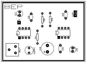
Figure 3: Actual size component side PCB
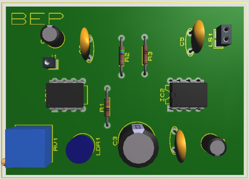
Figure 4: 3D view of Self Resetting LDR Alarm using Timer IC 555
Click Here to download PCB Diagram
PARTS LIST OF SELF RESETTING ALARM USING TIMER IC 555
| Resistors (all ¼-watt, ± 5% Carbon else Specified) |
| R1 = 100 KΩ
R2 = 5.6 KΩ R3 = 1 KΩ VR1 = 100 KΩ (Potentiometer) |
| Capacitors |
| C1 = 100 µF, 10V (Electrolytic Capacitor)
C2, C5 = 0.01 µF (Ceramic Disc) C3 = 1000 µF, 10V (Electrolytic Capacitor) C4 = 0.47 µF (Ceramic Disc) C6 = 100 µF, 10V (Electrolytic Capacitor) |
| Semiconductors |
| IC1, IC2 = NE555 (Timer IC) |
| Miscellaneous |
| LDR
LS1 = 4Ω Loudspeaker |