GPS (Global Positioning System) is getting more popular these days because of its application and uses in electronic project. Today, we are going to build a digital cock solely based on GPS module. The project “Arduino GPS Digital Clock” collects information from the satellite in the form of 70-character long string and show only date and time. In this article we will show you how to extract exact date and time from the string ($GPRMC) that received by GPS Module.
Components used in Arduino GPS Digital Clock
- Arduino UNO Board
- GPS Module
- 16×2 LCD
- 1K resistor
- 10K Potentiometer
- Connecting Wires
Arduino UNO Board:
The central component or processing component of the projects Arduino GPS Digital Clock is arduino uno board. As we know that arduino is open source device thus use of this board is more easy and flexible. This board is based on AVR family microcontroller ATmega 328/ATmega328P. Some silent features of arduino board are:
- 14 Digital input/output pin (same pin can be used for as well as output)
- 6 analog input pins (can also be used as digital)
- Inbuilt 32K flash memory
- 16MHz crystal oscillator
- USB connection for serial connection
- ISCP Header
- Reset button and dedicated 9V power supply Jack
As this board contains microcontroller, thus it is programmable and can be programmed using arduino IDE software.
GPS Receiver
In our prototype we had used SIM808 EVB-V3.2 module from SIMCOM. SIM808 module is GSM/GPRS, GPS and Bluetooth development board. Silent features of SIM808
- More option for power interface i.e. DC044, V_IN and a lithium battery interface.
- Micro USB interface for firmware update
- Can be used as GSM/GPRS, GPS and Bluetooth at a time.
- Single channel voice and single channel mic. Interface.
Due to this feature this module is very much popular among electronic hobbyist.
LCD Module: For this prototype we are using 16X2 alphanumeric LCD. This LCD display day and time.
Circuit Description of Arduino GPS Digital Clock
The circuit of arduino GPS Digital Clock is shown in figure 1. The project encompassed GPS modem (SIM 808) as the core components of the projects along with arduino uno board and LCD module. This project offers most accurate date and time and can be used at any public place like Mall, Bus stand etc.
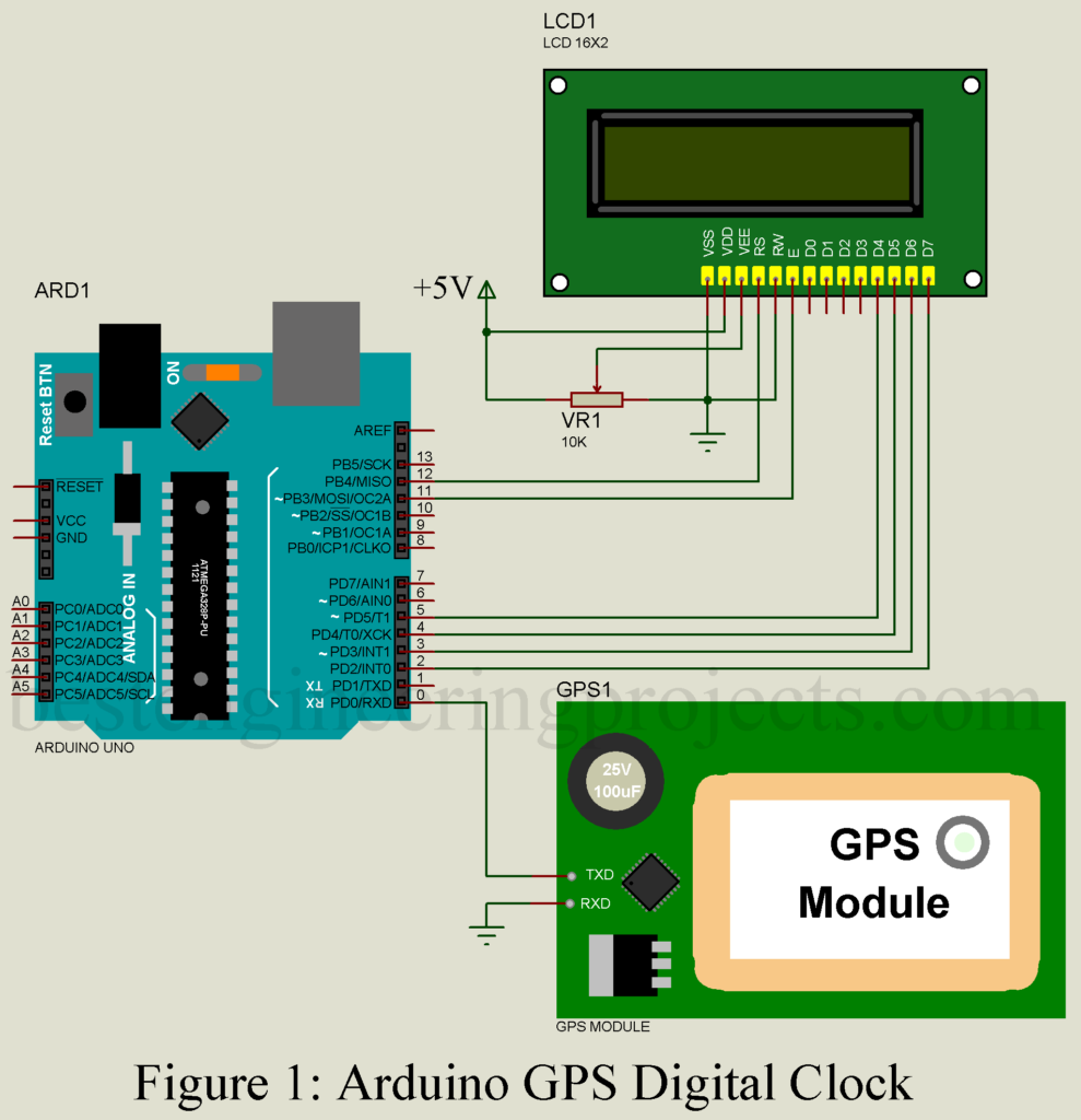
Wiring of the circuit is very simple, GSM/GPS Module Tx pin is connected to Rx pin (D0) of arduino uno board and Rx pin of module is grounded as shown in circuit diagram. Arduino uno board ground and GSM/GPS ground should be connected to each other.
A 16X2 LCD does the task of displaying the date and time on its screen. We all know that LCD operates on two modes i.e. 4 bit mode and 8 bit mode. For this project, we will use 4-bit mode. <LiquidCrystal.h> library function make interface of arduino uno board and LCD easier. The digital pin of arduino D11 and D12 is connected to Enable (E) and Set/Reset (RS) of LCD. Similarly, arduino pin D5, D4, D3 and D2 are linked with data pin D4 to D7 (higher order data pin) of LCD respectively as shown in circuit diagram.
LED+ pin (pin 15) of LCD is conned to +5V supply through 1K-ohm resistor and LED- pin (pin 16) of LCD is connected to GND pin.
More other electronic project based on GPS posted in bestengineeringprojects.com
- Accident Detection and Alert System using Arduino
- GPS and GSM based Vehicle Tracking System
- GPS Navigator Circuit using ATmega 16
- DIY Distance Measurement using GPS and ATmega328P
Software Code | Arduino GPS Digital Clock
Software code is written in arduino programming language and compiled using arduino IDE. The software part is simple and easy to understand. This program checks the data from GPS receiver and extract only $GPRMC string which contains date and time and display it on LCD.
|
1 2 3 4 5 6 7 8 9 10 11 12 13 14 15 16 17 18 19 20 21 22 23 24 25 26 27 28 29 30 31 32 33 34 35 36 37 38 39 40 41 42 43 44 45 46 47 48 49 50 51 52 53 54 55 56 57 58 59 60 61 62 63 64 65 66 67 68 69 70 71 72 73 74 75 76 77 78 79 80 81 82 83 84 85 86 87 88 89 90 91 92 93 94 95 96 97 98 99 100 101 102 103 104 105 106 107 108 109 110 111 112 113 114 115 116 117 118 119 120 121 122 123 124 125 126 127 128 129 130 131 132 133 134 135 136 |
#include<LiquidCrystal.h> #include <DFRobot_sim808.h> #include <SoftwareSerial.h> LiquidCrystal lcd(12, 11, 5, 4, 3, 2); char str[70]; char *test="$GPRMC"; int temp,i; DFRobot_SIM808 sim808(&Serial); void setup() { Serial.begin(9600); lcd.begin(16,2); lcd.setCursor(0,0); lcd.print("GPS DigitalClock"); lcd.setCursor(0,1); lcd.print("Best Engg. Proj."); delay(300); if( sim808.attachGPS()) Serial.println("Open the GPS power success"); else Serial.println("Open the GPS power failure"); } void loop() { serial1Event(); if (temp) { lcd.clear(); int str_lenth=i; int x=0,comma=0; String UTC_hour=""; String UTC_minut=""; String UTC_second=""; String UTC_date=""; String UTC_month=""; String UTC_year=""; String str1=""; while(x<str_lenth) { if(str[x]==',') comma++; if(comma==1) { x++; UTC_hour+=str[x++]; UTC_hour+=str[x++]; UTC_minut+=str[x++]; UTC_minut+=str[x++]; UTC_second+=str[x++]; UTC_second+=str[x]; comma=2; } if(comma==10) { x++; UTC_date+=str[x++]; UTC_date+=str[x++]; UTC_month+=str[x++]; UTC_month+=str[x++]; UTC_year+=str[x++]; UTC_year+=str[x]; } x++; } int UTC_hourDec=UTC_hour.toInt(); int UTC_minutDec=UTC_minut.toInt(); int Second=UTC_second.toInt(); int Date=UTC_date.toInt(); int Month=UTC_month.toInt(); int Year=UTC_year.toInt(); int Hour=UTC_hourDec+5;//change hour according to your time zones if(Hour>23) { Hour-=24; Date+=1; } int Minut=UTC_minutDec+45;//change minutes according to your time zones if(Minut>59) { Minut-=60; Hour+=1; } // UTC_Nepal_zone_time lcd.clear(); lcd.print("Date: "); lcd.print(Date); lcd.print("/"); lcd.print(Month); lcd.print("/"); lcd.print("20"); lcd.print(Year); lcd.setCursor(0,1); lcd.print("Time: "); lcd.print(Hour); lcd.print(":"); lcd.print(Minut); lcd.print(":"); lcd.print(Second); // delay(100); temp=0; // j=0; i=0; x=0; str_lenth=0; // k=0; } // delay(1000); } void serial1Event() { while(1) { while (Serial.available()) //checking serial data from GPS { char inChar = (char)Serial.read(); str[i]= inChar; //store data from GPS into str[] i++; if (i < 7) { if(str[i-1] != test[i-1]) //checking for $GPRMC sentence { i=0; } } if(i>65) { temp=1; break; } } if(temp) break; } } |
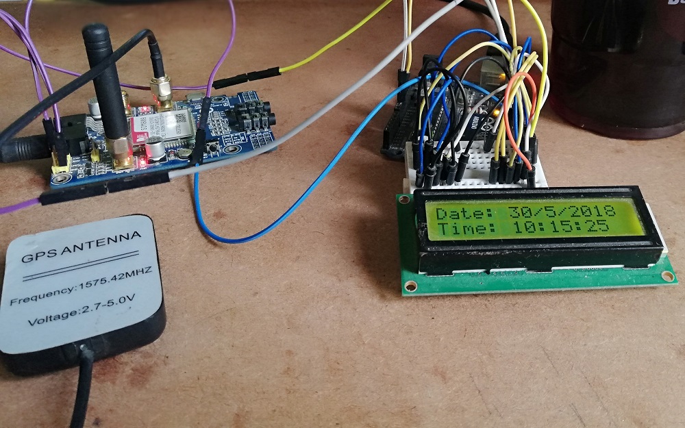
The author prototype