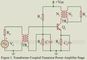
Transformer Coupled Audio Power Amplifier: Untuned large signal amplifier (power amplifier) of class AB and B type invariably use transformer coupled stages while those of class A type also generally use transformer coupled stage. RC coupled stages are not used because the quiescent current flawing through the load resistor results in large wastage of dc power in it. This dc power dissipated in the load resistor does not contribute to the useful ac output power. Further flow of dc current through the output device is not desirable. Hence it is…
Read MoreCategory: Transistor Amplifiers
Harmonic Distortion in Amplifier
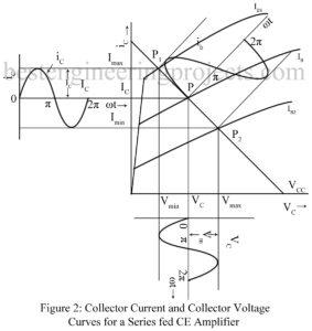
Second Harmonic Distortion in Amplifier In the graphical analysis given in the preceding article, the amplifying device is assumed to be preferable linear. Thus, we have assumed the output characteristics to be linear, parallel and equi-spaced for equal increments of the parameter. Then the corresponding dynamic transfer characteristic is also linear. Thus, linear amplification requires dynamic transfer characteristic to be linear. In practice, however, the dynamic transfer characteristic is never truly linear. For optimum linearity of amplification using the available amplifying device, we operate over such small region of dynamic…
Read MoreLarge Signal Amplifier | Power Amplifier
Large Signal Amplifier | Power Amplifier: In a multistage amplifier, first stage or the input stage and the intermediate stage are usually small signal class A amplifier stage while the last stage (the output stage) or sometimes last two stage are large signal amplifier (power amplifier) stage. Small signal amplifier stages serve to amplify the weak input signal to a sufficient large value to drive the final stage. The output stage generally feeds a transducer such as CR Tube, a loud speaker, a servo-control motor etc. the large signal amplifier…
Read MoreTransformer Coupled CE Amplifier
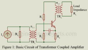
Figure 1 gives the basic circuit of a transformer coupled CE amplifier stage. In figure 1, a current source Is having shunt source resistance Rs drives the amplifier through a transformer TR1. Load resistance RL is fed from the collector output circuit through a transformer TR2. A transformer coupled CE amplifier finds following applications: As input stage of a multistage simplified and usually driven by a microphone. As output stage feeding the load impedance and As intermediate stage Transformer coupling permits impedance matching thereby resulting in greater power gain. The…
Read MoreResistance Capacitance Coupled or R.C. Coupled Amplifier
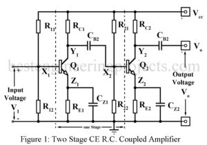
Resistance Capacitance Coupled or R.C. Coupled Amplifier Figure 1 gives the circuit of a two-stage common emitter R.C. coupled amplifier while figure 2 gives the circuit of a two-stage common source (CS) FET R.C. coupled amplifier. Typical component values are also indicated. In both amplifier circuits of Figure 1 and 2, X1 and Y1 are the input and output terminals of the first stage. The output at Y1 is coupled to the input X2 of the second stage through a coupling capacitor Cb2. This capacitor serves another function of blocking…
Read MoreCascading of Amplifier Stages
What is Cascading of Amplifier Stages? A single stage of amplifier can provide only a limited current gain or voltage gain. Most of the applications require much higher gain. Hence, we usually use several amplifier stages connected in cascade i.e. connected such that the output of one stage becomes the input to the next stage. Thus, a multistage amplifier or cascade amplifier may provide a higher voltage gain or current gain. Cascading of amplifier stages is usually done to increase the total gain of the amplifier. However, sometimes cascading is…
Read MoreClassification of Amplifiers
Amplifiers may be classified or Classification of Amplifiers in several ways as described below: According to the Frequency Range | Classification of Amplifiers Thus amplifiers may be classified as below: DC (Direct coupled) Amplifiers from zero frequency (dc) onwards. Audio Frequency Amplifiers 20 Hz to 20 KHz Video Frequency Amplifiers up-to a few MHz. Radio Frequency (RF) Amplifiers from a few KHz to hundreds of MHz. Ultra-high Frequency (UHF) and Microwave Amplifier up-to hundred or thousands of MHz. According to the method of operation | Classification of Amplifiers The position of the…
Read MoreApproximate h-model of CE, CB, CC amplifier
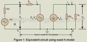
Approximate h-model: In the analysis of the transistor amplifier, we have as far used the exact h-model for the transistor. In practice, we may conveniently use an approximately h-model for the transistor which introduces an error of < 10% in most cases. This much error may be conveniently tolerated since the h-parameters themselves are not steady but vary considerably for the same type of transistor. We first derive this approximate CE h-model. Figure 1 gives the equivalent circuit of the CE amplifier using the exact h-model for the CE transistor.…
Read MoreComparison of CE, CB and CC Configurations
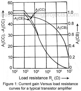
Comparison of CE, CB and CC Configurations: It is useful to study the variation of AI, AV and Ri with change in load resistance RL for each of the three configurations. Similarly, we may study variation of R0 with change of source resistance RS. Figure 1, 2 and 3 plots for each of the three configurations, current gain AI, voltage gain AV and input resistance Ri respectively as function of load resistance RL for the typically transistor whose h-parameters are given in Table 4.1. From these curves we get the…
Read MoreCommon Collector Amplifier or the Emitter Follower
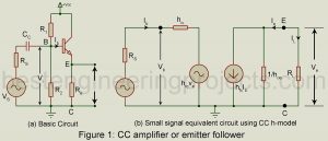
Common Collector Amplifier or the Emitter Follower: Figure 1(a) gives the basic circuit of a common collector amplifier, popularly called emitter follower. Its voltage gain is close to unity (one) and, therefore, any increment in the input voltage i.e. the base voltage appears as an equal increment in the output voltage across the load resistor in the emitter circuit. Thus, the emitter may be said to follow the input signal and hence the name emitter follower. The input resistance Ri of a CC amplifier or emitter follower is very high,…
Read More