Comparison of CE, CB and CC Configurations: It is useful to study the variation of AI, AV and Ri with change in load resistance RL for each of the three configurations.
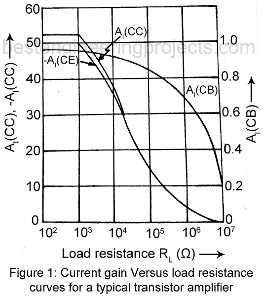
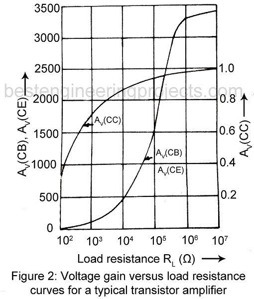
Similarly, we may study variation of R0 with change of source resistance RS. Figure 1, 2 and 3 plots for each of the three configurations, current gain AI, voltage gain AV and input resistance Ri respectively as function of load resistance RL for the typically transistor whose h-parameters are given in Table 4.1.
From these curves we get the following information:
(A) CE Amplifier | Comparison of CE, CB and CC Configurations
AI is high for 
AV is high for usual values of RL. Typical value of RL is 
Ri is medium (about  ) and varies nominally with variation of RL.
R0 is moderately high and varies appreciably with variation of RS.
Uses: CE amplifier is capable of providing moderately high values of both AI and AV. Hence it is popularly used.
Table 1 Approximate Conversion Formulas for h-parameter |
|
 |
 |
 |
 |
 |
 |
 |
 |
(B) CB Amplifier | Comparison of CE, CB and CC Configurations
AI < 1 and its magnitude decreases with increase of RL beyond  , reaching a value of about 0.2 for
  .
.
AV is high for usual value of RL.
Ri is low ( ), being lowest of all the three configurations.
R0 is high  , being highest of all the three configurations.
Uses: CB amplifier is not used as an amplifier for providing voltage or current gain. It is used only:
- For matching a very low impedance source to the high input impedance of the main amplifier.
- As a noninverting amplifier with AV > 1.
- For driving a high impedance load.
- As a constant current source for use in a sweep (time-base) voltage generator or to charge a capacitor linearly with time.
(C) CC Amplifier | Comparison of CE, CB and CC Configurations
AI is high, almost equal to that of CE amplifier for 
AV <1
Ri is high, being highest of all the three configurations.
R0 is low, being lowest of all the three configurations.
Uses: It is used as a buffer amplifier between a high impedance source and a low impedance load.
Table 2 gives the value of AI, AV, AP, Ri, and R0 for a typical transistor (h-parameters given in table 1) for all the three configurations using  and
and  . Actually, these values of AI, Ri, AV, R0 and AP are picked up randomly.
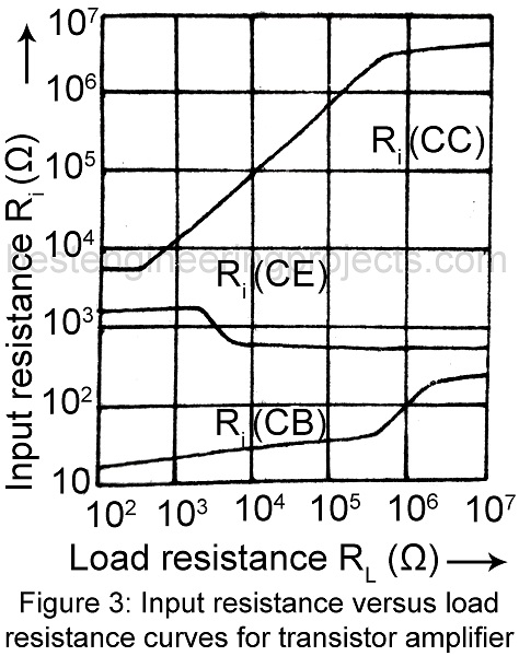
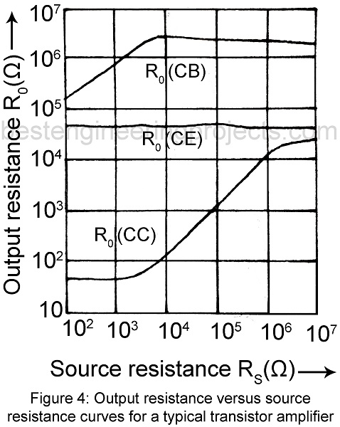
Table 2: Performance Schedule of Typical Transistor in CE, CB and CC Configurations |
|||
| Quantity | CE | CB | CC |
| AI | -45 | 0.98 | 46 |
| AV | -172 | 169 | 0.99 |
| AP | 7817 | 166 | 46 |
| Ai |  |
 |
 |
| R0 |  |
 |
 |