Amplitude modulation is generated by combining carrier and intelligence frequencies through a nonlinear device. Diodes have nonlinear areas, but they are not often used because, being passive devices, they offer no gain. Transistors offer nonlinear operation (if properly biased) and provide amplification, thus making them ideal for this application. Figure 2 shows an input/output relationship for a typical bipolar junction transistor (BJT). Notice that at both low and high values of current, nonlinear areas exist. Between these two extremes is the linear area that should be used for normal amplification. One of the nonlinear areas must be used to generate AM.
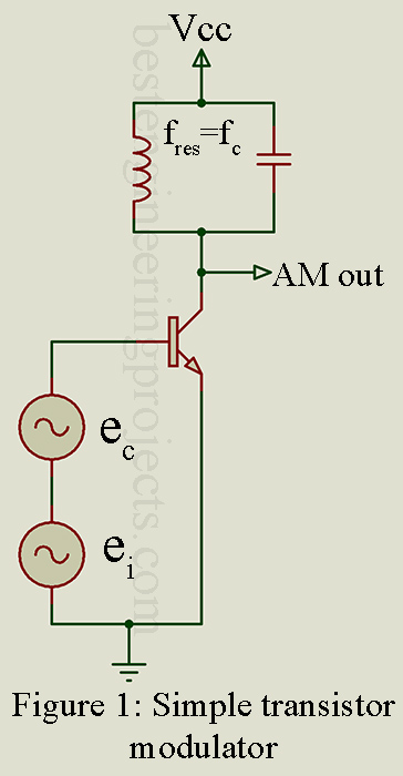
Figure 1 shows a very simple transistor modulator. It operates with no base bias and thus depends on the positive peaks of ec and ei to bias it into the first nonlinear area shown in Figure 2. Proper adjustment of the levels of ec and ei is necessary for good operation. Their levels must be low to stay in the first nonlinear area, and the intelligence power must be one-half the carrier power (or less) for 100% modulation (or less). In the collector, a parallel resonant circuit, tuned to the carrier frequency, is used to tune into the three desired frequencies-the upper and lower side bands and the carrier. The resonant circuit presents a high impedance to the carrier (and any other close frequencies such as the sidebands) and thus allows a high output to those components, but it’s very low impedance to all other frequencies effectively shorts them out. Recall that the mixing of two frequencies through a nonlinear device generates more than just the desired AM components. The tuned circuit then “sorts” out the three desired AM components and serves to provide good sinusoidal components by the flywheel effect.
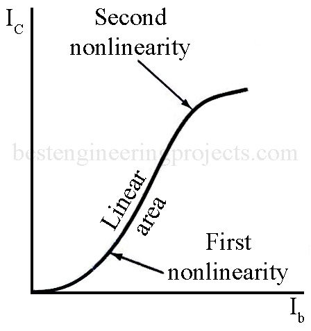
Figure 2: Transistor curve
In practice, amplitude modulation can be obtained in a number of ways. For descriptive purposes, the point of intelligence injection is utilized. For example, in Figure 1 the intelligence is injected into the base, hence it is termed base modulation. Collector and emitter modulation is also used. In previous years, when vacuum tubes were widely used, the most common form was plate modulation, but the grid, cathode, and (for pentodes) suppressor-grid and screen-grid modulation schemes were also utilized.