In this article, you will see how to interface GP2Y1010AU0F Dust Sensor with Arduino. GP2Y1010AU0F is an optical dust sensor that can detect very fine particles such as smoke, environmental dust, etc. It is designed for application in commercial air purifiers. However, it is also used in air conditioners and portable air quality monitoring systems. This sensor can detect dust particles up to the size of 0.5 µm.
Features of Dust Sensor GP2Y1010AU0F
- Can easily differentiate smoke and house dust
- Consumes less current: 20mA max
- Sense dust particles in less than a second
- Detect dust particles up to the size of 0.5 µm
- Lead-free
Specifications of Dust Sensor GP2Y1010AU0F
- Operating voltage: 4.5V to 5.5V (DC)
- Sensor sensitivity: 0.5 V/ (100 µ/m3)
- Operating Temperature: -10 ºC to +65 ºC
- Minimum detectable dust size: 0.5 µm
- Output Interface: Analog
- Dust Density Sensing Range: Up to 580 µg/m3
Components Required
- Arduino Uno/Nano x 1
- GP2Y1010AU0F Dust Sensor x 1
- Jumping Wires
- Capacitor 220 µF x 1
- Resistor 150 Ω x 1
- Breadboard x 1
- DC Power Supply 5V
- 20 x 4 LCD Module x 1
Working principle
The optical dust sensor operates on the light scattering principle. It consists of a LED emitter and a phototransistor which are positioned at one another. As dust-laden air enters the sensor chamber, it scatters light from the LED emitter toward the phototransistor. The intensity of the dispersed light increases with the increase in dust concentration inside the sensor chamber. The dust sensor produces a voltage value that fluctuates depending on the strength of the scattered light, which relates to the amount of dust in the air. The output voltage value can then be used linearly to determine the absolute dust density.
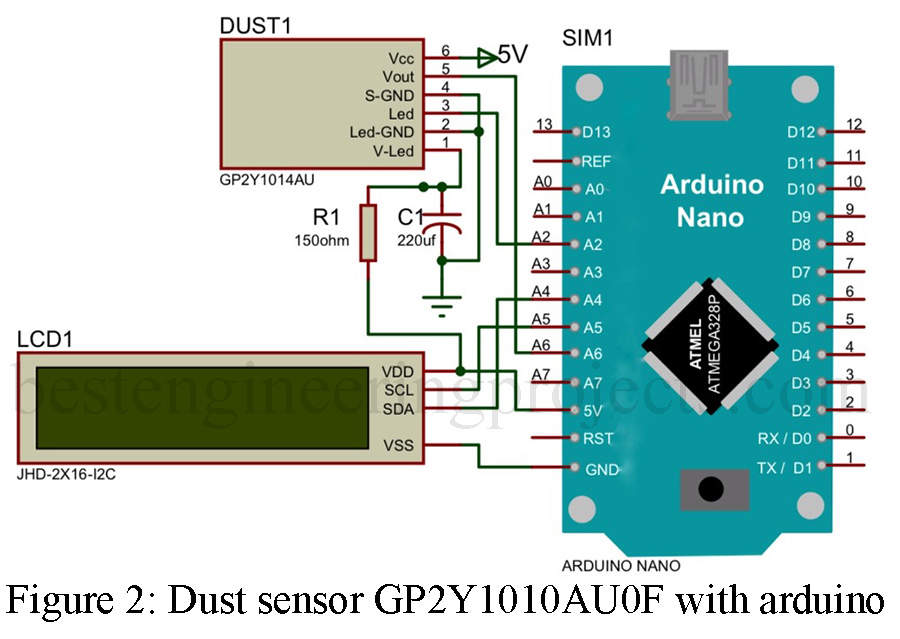
Circuit Description of Dust Sensor with Arduino
Connecting GP2Y1010AU0F dust sensor with Arduino is simple as shown in the circuit diagram. First, connect the Vcc pin of the dust sensor module to the 5V pin of the Arduino. V-LED is also connected to the 5V using 150 Ω resistors. The sensor’s LED-GND and S-GND should be connected to the GND pin of the Arduino. The LED pin of the sensor should be connected to the Analog pin A2 of the Arduino. Here analog pin A2 is used as the digital output pin. The dust sensor produces analog voltage thus Vo pin of the module is connected to an analog input pin i.e. A6 of Arduino. A pulse driver circuit is also required and is designed around a resistor of value 150 Ω and capacitor of value 220uF. In order to visualize the dust concentration an I2C LCD is also added. Connecting I2C LCD is simple. Vcc and GND of LCD are connected to +5V and GND of Arduino where SDA and SCL pin of LCD is connected to A4 and A5 of Arduino respectively.
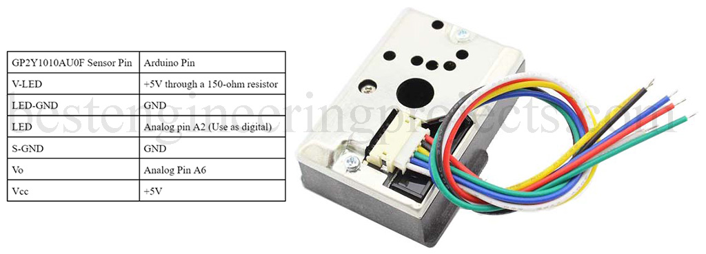
| GP2Y1010AU0F Sensor Pin | Arduino Pin |
| V-LED | +5V through a 150-ohm resistor |
| LED-GND | GND |
| LED | Analog pin A2 (Use as digital) |
| S-GND | GND |
| Vo | Analog Pin A6 |
| Vcc | +5V |
Software Code of Dust Sensor with Arduino:
The code for the Dust sensor with Arduino is written in Arduino programming language (C\C++) and is compiled using Arduino IDE. Here in this program, we are using only one library i.e. for I2C LCD. The program basically switches ON/OFF the internal LED and reads the analog voltage. For switching the LED we are using analog pin A2 and used it as a digital output. According to the datasheet of GP2Y1010AU0F, the internal LED is configured as a low trigger i.e. when the output of Arduino A2 becomes low the internal LED becomes ON.
At first, we turn ON the internal LED for 280ms and then measure the output voltage for 40ms and then turn OFF the LED. For stable reading, we are taking 10 different values and later we calculate the average as shown in the code. The minimum time interval for two conjugative readings must be equal to or greater than 1000ms else it shows an error.
The average analog value is now converted to a voltage by multiplying 5 and dividing by 1024. Now, this value is converted to dust density by using the formula for a straight line i.e. y=mx+c.
Whereas y = dust density (need to calculate)
m = 0.17
x = measured voltage
c = -0.1 (constant)
Here in this code, we are calculating the ug/m3 instead of mg/m3, for that we are multiplying the multiplier (m) by 1000 as shown in the code. The value of Y is the required dust density in um/m3.
|
1 2 3 4 5 6 7 8 9 10 11 12 13 14 15 16 17 18 19 20 21 22 23 24 25 26 27 28 29 30 31 32 33 34 35 36 37 38 39 40 41 |
#include<LiquidCrystal_I2C.h> LiquidCrystal_I2C lcd(0x27,20, 4); int led= A2; //Using A2 pin as digital output Pin float voMeasured = 0; float calcVoltage = 0; float dustDensity = 0; void setup(){ Serial.begin(9600); pinMode(led,OUTPUT); lcd.backlight(); lcd.init(); } void loop(){ float totalVoltage = 0; for(int i=0;i<10;i++) { digitalWrite(led,LOW); delayMicroseconds(280); totalVoltage += analogRead(A6); Serial.println(totalVoltage); delayMicroseconds(10); digitalWrite(led,HIGH); delay(960); } Serial.print(totalVoltage); voMeasured = totalVoltage/10.0; calcVoltage = voMeasured/1024.0 * 5.0; Serial.println(calcVoltage); dustDensity = (170* calcVoltage -0.1); lcd.clear(); lcd.setCursor(4,0); lcd.print("Dust Density"); lcd.setCursor(4,1); lcd.print(dustDensity); lcd.print(" ug/m^3"); Serial.print("Dust Density:"); Serial.print(dustDensity); Serial.println("ug/m^3"); delay(960); } |
Applications:
- Air Purifiers
- Air Conditioner
- Portable Air Quality Monitoring System