IoT is getting popular and better day to day, due to its advantage like remote control, user-friendly, securer control of appliance, etc. So, today in this article we are going to design an IoT Based Device Controlled with Security using Node MCU. The reason of selection Node MCU for this project is cheap, powerful as well as Arduino compatible.
With the purposed design is shown below one can control different electrical devices securely. You can increase and decrease the number of devices according to your requirement with little modification in software code and circuit diagram.
Features of IoT Based Device Controlled with Security
- Secure: People with usernames and passwords can only control the device.
- No dedicated app is needed: One can control the device using any browser.
- Multiple device control: With the purposed design, one can control 4 devices at a time but can easily increase and decrease the number.
- Cheap and easy design: Node MCU is cheaper in comparison with other IoT devices and easy because it is Arduino friendly.
- Lockdown features: If any user enters username and password incorrectly three times, the system locks down for 3 minutes. This time can be increased and decreased.
Component Required
- Node MCU
- 4 x 1N4007 diode
- 4 x 12V Relay
- 4 x BC548
- 4 x 5K resistor
- 1 x LM7805
- 1 x 100 uF
Circuit Description IOT Based Device Controlled with Security:
The circuit “IOT Based Device Controlled with Security” shown in figure 1 is very simple and straightforward. This circuit contains node MCU and for switching circuit. This node MCU is used to switch ON and OFF the appliance according to the command we give online.
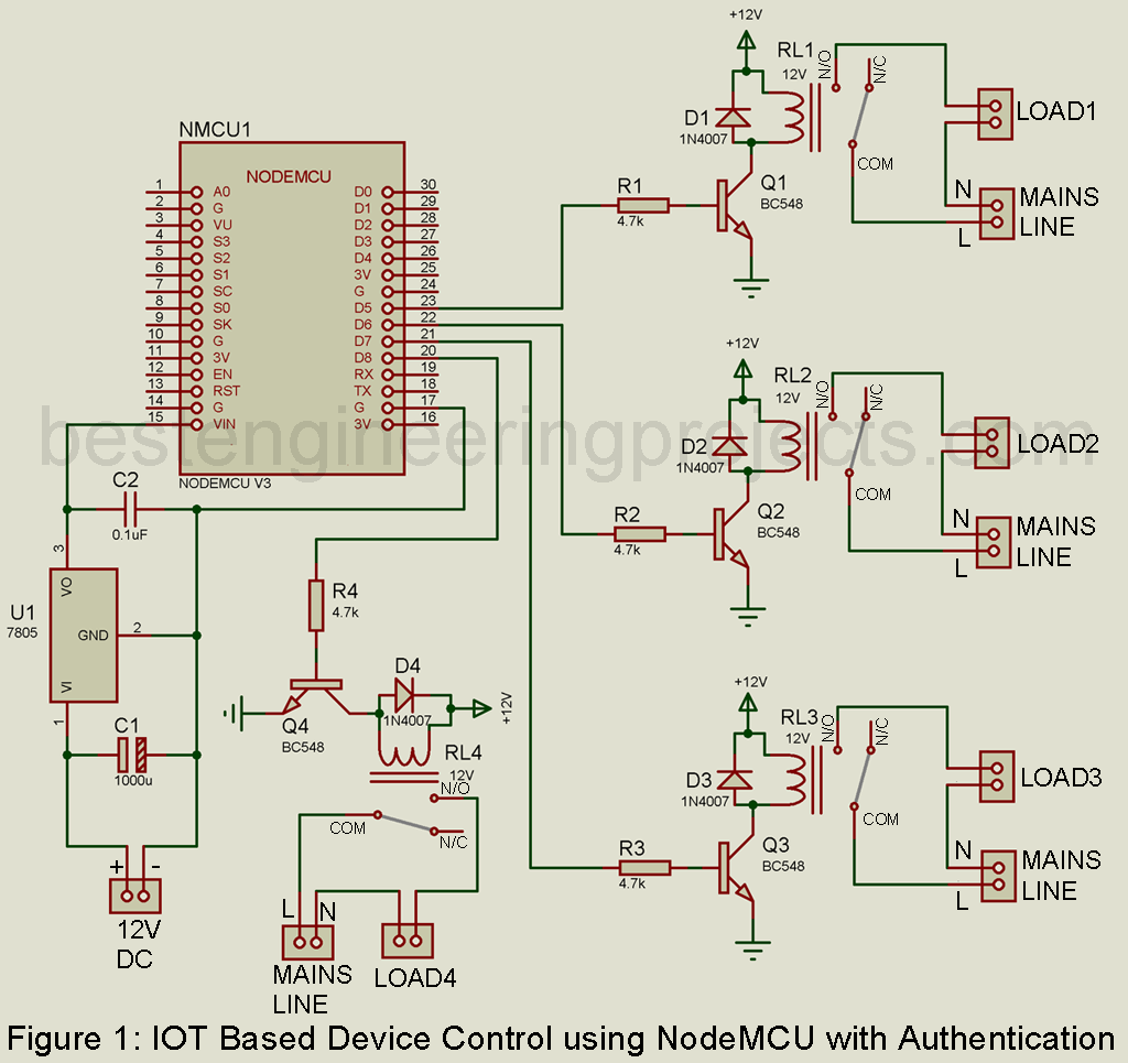
Switching Circuit:
The switching circuit is designed around transistor BC548 and relay. These four switching circuits are identical. The signal from node MCU is given to the base of the transistor which energizes the relay and switch on the device.
A diode is connected across the relay coil to protect the control circuit from flyback voltage from the relay coil. Mains line is given to mains line connector where four devices are connected to four connectors (Load 1 to Load 4).
Here, we are using Node MCU based on ESP8266 for controlling all switches. As we are controlling four devices, four digital pins are used i.e. D5, D6, D7, and D8.
Software for IoT Based Device Controlled with Security:
Before going to software code, we have to configure Arduino IDE to program Node MCU using Arduino IDE.
Please check the previous article on how to configure ARDUINO IDE for programming Node MCU. How to configure Arduino IDE Node MCU
Now it’s time to get your IP Address. For that go to the website link “https://tttapa.github.io/ESP8266/Chap07%20-%20Wi-Fi%20Connections.html” and upload station mode code to your Node MCU and then open the serial monitor (Ctrl + Shift + M). There you will get your IP address. Note it down, because this IP address is your URL where you can control your device (Switch ON and OFF).
Screenshot for web-page
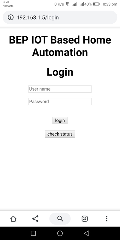
Figure 2: Web Login Page
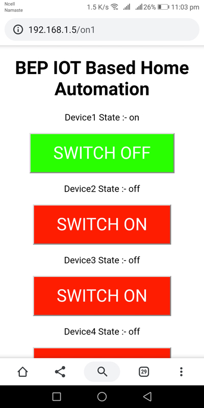
Figure 3: Device Control Page
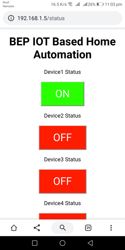
Figure 4: Device Status Page
The function used in Software:
When we type the URL (IP Address) this function is called to check the status. void statusCheck()
|
1 2 3 4 5 6 7 8 9 10 11 12 13 14 15 16 17 18 19 20 21 22 |
void statusCheck(){ //webpage for status String check = ""; check += pageData; check += "<meta http-equiv='refresh' content='"; check += refreshTime; check += "'>"; for(int x=0; x<=3; x++) { check += "<p>Device"; check += x+1; check += " Status</p>"; if (deviceState[x]=="off") { check += "<p><button class=\"button\">OFF</button></a></p>"; } else { check += "<p><button class=\"button1\">ON</button></a></p>"; } } check += "<div id=\"login\"> <form action='/login' method='POST'> <br><button type='submit' name='submit'>login</button></center> </form>"; check += "</body></html>"; server.send(200, "text/html", check); } |
This function is used to generate 32-bit cookies from random characters. void generate cookie()
|
1 2 3 4 |
void genrateCookie(){ // used to generate Cookie sessionCookie = ""; for(int i = 0; i < 32; i++) sessionCookie += ranchars[random(0, ranchars.length())]; //Used to generate 32-bit cookie using random characters from ranchars string } |
This function is used to check whether cookies are valid or not. bool if_authenticated()
|
1 2 3 4 5 6 7 |
bool if_authenticated(){ //This function checks for Cookie if (server.hasHeader("Cookie")){ String cookie = server.header("Cookie"), authk = "c=" + sessionCookie; if (cookie.indexOf(authk) != -1) return true; } return false; } |
This function is used to check the status of output pins. void pinControl()
|
1 2 3 4 5 6 7 8 9 10 11 12 13 14 15 16 17 |
void pinControl(int pin, int pinData){ if(if_authenticated()){ // check loged in or not if loged in switch on the device inactiveTime = millis(); if (pinData ==0){ deviceState[pin] = "off"; digitalWrite(device[pin], LOW); } else{ deviceState[pin] = "on"; digitalWrite(device[pin], HIGH); } handleRoot(); } else{ // if not loged in redirect to /login page logout(); } } |
This function is used to generate the webpage where background_color is used to change the color of the button. void webPage()
|
1 2 3 4 5 6 7 8 9 |
void webPage(){ pageData = "<!DOCTYPE html><html>"; pageData += "<head><meta name=\"viewport\" content=\"width=device-width, initial-scale=1\">"; pageData += "<style>html { font-family: Helvetica; display: inline-block; margin: 0px auto; text-align: center;}"; pageData += ".button { background-color: #ff1d00; color: white; padding: 16px 40px; font-size: 30px; margin: 2px; cursor: pointer;}"; pageData += ".button1 {background-color: #2aff00; color: white; padding: 16px 40px; font-size: 30px; margin: 2px; cursor: pointer;}"; pageData += "</style></head>"; pageData += "<body><h1>" + headingMessage + "</h1>"; } |
This function is used to handle invalid webpage requests. void handle not found()
|
1 2 3 4 5 6 7 8 |
void handleNotFound(){ //webpage for invalid webaddress String invalidPage = ""; invalidPage += pageData; invalidPage += "<center><br>Invalid Page Request<p></p>"; invalidPage += "<div id=\"login\"> <form action='/login' method='POST'> <br><button type='submit' name='submit'>HOMEPAGE</button></center> </form>"; invalidPage += "</body></html>"; server.send(200, "text/html", invalidPage); } |
This function handles the login page and is responsible for the invalid count and lock user. void handleLogin()
|
1 2 3 4 5 6 7 8 9 10 11 12 13 14 15 16 17 18 19 20 21 22 23 24 25 26 27 28 29 30 31 32 33 34 35 36 37 38 39 40 41 42 43 44 |
void handleLogin(){ if (server.hasHeader("Cookie")){ String cookie = server.header("Cookie"); } if (server.hasArg("user") && server.hasArg("pass")){ if (server.arg("user") == username && server.arg("pass") == loginPassword && !lock){ //check login details are true or not and dont allow if device is in lockdown header = "HTTP/1.1 301 OK\r\nSet-Cookie: c=" + sessionCookie + "\r\nLocation: /\r\nCache-Control: no-cache\r\n\r\n"; //if above values are ture, send Cookie server.sendContent(header); trycount = 0; //reset trycount return; } message = "<center><br>"; if (trycount != noOfTry && !lock)trycount++; //if system is not locked, increase trycount if (trycount < noOfTry && !lock){ //user is given predefined number of times to use invalid login details after that the system is locked down message += "Invalid username/password<p></p>"; message += (noOfTry - trycount); message += " tries left before system temporarily locks down"; loginTime = millis(); // reset the loginTime timer, since number of tries is left } if (trycount == noOfTry){ // If invalid try is more than number of try allowed if(lock){ message += "Too much invalid login attempts, you can use this system in "; message += timeInMin - ((millis() - loginTime) / 60000); //Display lock time remaining in minutes message += " minutes"; } else{ loginTime = millis(); lock = true; message += "Too much invalid login attempts, you can use this system in 3 minutes"; //This happens when your device locks down for first time } } } String loginPage = ""; loginPage += pageData; loginPage += "<body> <div id=\"login\"> <form action='/login' method='POST'> <center> <h1>Login </h1><p><input type='text' name='user' placeholder='User name'></p><p><input type='password' name='pass' placeholder='Password'></p><br><button type='submit' name='submit'>login</button></center> </form>"; loginPage += "<div id=\"status\"> <form action='/status' method='POST'> <center> <br><button type='submit' name='submit'>check status</button></center> </form></body></html>"; loginPage += message + "</center>"; server.send(200, "text/html", loginPage); //merge loginPage and message and send it message=""; //empty message string } |
Code Modification: You have to modify some parts of the code.
Operation mode: Here you decide the operating mode of ESP8266 (STA or APM).
|
1 |
#define stationMode true |
WiFi Configuration: Here you have to set your SSID name and its Password.
|
1 2 |
const char* ssid = "netis"; //string used to store access point name const char* password = "password"; //string used to store access point password |
Logging Details: Here you have to set logging user name and password.
|
1 2 |
String username = "admin"; //string used to store username String loginPassword = "admin"; //string used to store password |
Header Message: Edit your header here.
|
1 |
String headingMessage = "BEP IOT Based Home Automation"; |
Wrong Attempt: Number of the wrong attempts allowed (after that user will be locked down).
|
1 |
int noOfTry = 10; |
Lockdown Time: Lockdown time when the user exceeds the wrong attempt.
|
1 |
int lockDownTime = 180000;//times in milliseconds 180000 = 180 seconds |
Cookies Time: The time for cookies expire
|
1 |
int cookieExpireTime = 60000;// times in milliseconds 60000 = 60 seconds |
Refresh Time: Time for the refreshing webpage for a status check.
|
1 |
int refreshTime = 10; time in seconds |
After changing the code according to your requirement upload the entire code to your Node MCU. And your IOT device is ready.
|
1 2 3 4 5 6 7 8 9 10 11 12 13 14 15 16 17 18 19 20 21 22 23 24 25 26 27 28 29 30 31 32 33 34 35 36 37 38 39 40 41 42 43 44 45 46 47 48 49 50 51 52 53 54 55 56 57 58 59 60 61 62 63 64 65 66 67 68 69 70 71 72 73 74 75 76 77 78 79 80 81 82 83 84 85 86 87 88 89 90 91 92 93 94 95 96 97 98 99 100 101 102 103 104 105 106 107 108 109 110 111 112 113 114 115 116 117 118 119 120 121 122 123 124 125 126 127 128 129 130 131 132 133 134 135 136 137 138 139 140 141 142 143 144 145 146 147 148 149 150 151 152 153 154 155 156 157 158 159 160 161 162 163 164 165 166 167 168 169 170 171 172 173 174 175 176 177 178 179 180 181 182 183 184 185 186 187 188 189 190 191 192 193 194 195 196 197 198 199 200 201 202 203 204 205 206 207 208 209 210 211 212 213 214 215 216 217 218 219 220 221 222 223 224 225 226 227 228 229 230 231 232 233 234 235 236 237 238 239 240 241 242 243 244 245 246 247 248 249 250 251 252 253 254 255 256 257 258 259 260 261 262 263 264 265 266 267 268 269 270 271 272 273 274 275 276 277 278 279 280 281 |
#include <ESP8266WiFi.h> #include <ESP8266WebServer.h> #define stationMode true // use to set ESP8266 in station mode or in Soft acess point mode const char* ssid = "netis"; //string used to store access point name const char* password = "password"; //string used to store access point password bool lock = false; //used to check device lockout String ranchars = "abcdefghijklmnopqrstuvwxyz0123456789"; //this will be used to generate random characters for cookie String username = "admin"; //string used to store username String loginPassword = "admin"; //string used to store password String headingMessage = "BEP IOT Based Home Automation"; String message = ""; String header = ""; String pageData = ""; String sessionCookie = ""; // cookie buffer String deviceState[] = {"off", "off", "off", "off"}; // variable to store the current output state unsigned long loginTime = millis(); // timer for logintime unsigned long inactiveTime = millis(); // timer for inactivity int noOfTry = 10; // noOfTry is used store the number of false entries allowed simultaneously int lockDownTime = 180000; //lockdown time in milliseconds int cookieExpireTime = 60000; //Cookie expire time in milliseconds int refreshTime = 10; // status check page refresh time const int device[] = {14,12,13,15}; // Assign output variables to nodemcu GPIO pins int trycount = 0; // trycount is used store the number of false entries made int timeInMin = lockDownTime/60000 -1; //lockdown time in minutes ESP8266WebServer server(80); void setup(void){ for(int x=0; x<=3; x++) { pinMode(device[x], OUTPUT); digitalWrite(device[x], LOW); } #if stationMode // for station mode WiFi.mode(WIFI_STA); WiFi.begin(ssid, password); while (WiFi.status() != WL_CONNECTED) // wait till wifi is connected { delay(500); } #else // for soft access point WiFi.mode(WIFI_AP_STA); WiFi.softAP(ssid, password); #endif genrateCookie(); //generate new Cookie webPage(); server.onNotFound(handleNotFound); server.on("/", handleRoot); server.on("/login", handleLogin); server.on("/on1", on1); server.on("/off1", off1); server.on("/on2", on2); server.on("/off2", off2); server.on("/on3", on3); server.on("/off3", off3); server.on("/on4", on4); server.on("/off4", off4); server.on("/logout", logout); server.on("/status", statusCheck); const char * headerKey[] = {"User-Agent","Cookie"} ; size_t headerKeySize = sizeof(headerKey)/sizeof(char*); server.collectHeaders(headerKey, headerKeySize ); //These 3 lines are used to collect User-Agent and Cookie in http header when request is made server.begin(); } void loop(void){ server.handleClient(); if(lock && abs(millis() - loginTime) > lockDownTime){ // after preset time is passed system is unlocked lock = false; trycount = 0; loginTime = millis(); } if(abs(millis() - inactiveTime) > cookieExpireTime){ // if there is no activity from loged in user,a new cookie is generated genrateCookie(); inactiveTime = millis(); } } void genrateCookie(){ // used to generate Cookie sessionCookie = ""; for(int i = 0; i < 32; i++) sessionCookie += ranchars[random(0, ranchars.length())]; //Used to generate 32-bit cookie using random characters from ranchars string } bool if_authenticated(){ //This function checks for Cookie if (server.hasHeader("Cookie")){ String cookie = server.header("Cookie"), authk = "c=" + sessionCookie; if (cookie.indexOf(authk) != -1) return true; } return false; } void handleRoot(){ if (!if_authenticated()){ //it checks if your cookie is valid or not. if not it redirects you to login page, if yes it sends you to main page header = "HTTP/1.1 301 OK\r\nLocation: /login\r\nCache-Control: no-cache\r\n\r\n"; server.sendContent(header); return; } inactiveTime = millis(); //reset the inactivity timer String mainpage = ""; mainpage += pageData; mainpage += "<meta http-equiv='refresh' content='"; mainpage += cookieExpireTime/1000 +2; mainpage += "'>"; for(int x=0; x<=3; x++) { mainpage += "<p>Device"; mainpage += x+1; mainpage += " State :- " + deviceState[x] + "</p>"; if (deviceState[x]=="off") { mainpage += "<p><a href=/on"; mainpage += x+1; mainpage += "><button class=\"button\">SWITCH ON</button></a></p>"; } else { mainpage += "<p><a href=/off"; mainpage += x+1; mainpage += "><button class=\"button1\">SWITCH OFF</button></a></p>"; } } mainpage += "<div id=\"logout\"> <form action='/logout' method='POST'> <br><button type='submit' name='submit'>logout</button></center> </form>"; mainpage += "</body></html>"; server.send(200, "text/html", mainpage); mainpage = ""; } void handleLogin(){ if (server.hasHeader("Cookie")){ String cookie = server.header("Cookie"); } if (server.hasArg("user") && server.hasArg("pass")){ if (server.arg("user") == username && server.arg("pass") == loginPassword && !lock){ //check login details are true or not and dont allow if device is in lockdown header = "HTTP/1.1 301 OK\r\nSet-Cookie: c=" + sessionCookie + "\r\nLocation: /\r\nCache-Control: no-cache\r\n\r\n"; //if above values are ture, send Cookie server.sendContent(header); trycount = 0; //reset trycount return; } message = "<center><br>"; if (trycount != noOfTry && !lock)trycount++; //if system is not locked, increase trycount if (trycount < noOfTry && !lock){ //user is given predefined number of times to use invalid login details after that the system is locked down message += "Invalid username/password<p></p>"; message += (noOfTry - trycount); message += " tries left before system temporarily locks down"; loginTime = millis(); // reset the loginTime timer, since number of tries is left } if (trycount == noOfTry){ // If invalid try is more than number of try allowed if(lock){ message += "Too much invalid login attempts, you can use this system in "; message += timeInMin - ((millis() - loginTime) / 60000); //Display lock time remaining in minutes message += " minutes"; } else{ loginTime = millis(); lock = true; message += "Too much invalid login attempts, you can use this system in 3 minutes"; //This happens when your device locks down for first time } } } String loginPage = ""; loginPage += pageData; loginPage += "<body> <div id=\"login\"> <form action='/login' method='POST'> <center> <h1>Login </h1><p><input type='text' name='user' placeholder='User name'></p><p><input type='password' name='pass' placeholder='Password'></p><br><button type='submit' name='submit'>login</button></center> </form>"; loginPage += "<div id=\"status\"> <form action='/status' method='POST'> <center> <br><button type='submit' name='submit'>check status</button></center> </form></body></html>"; loginPage += message + "</center>"; server.send(200, "text/html", loginPage); //merge loginPage and message and send it message=""; //empty message string } void logout(){ //webpage for /logout header = "HTTP/1.1 301 OK\r\nSet-Cookie: c=0\r\nLocation: /login\r\nCache-Control: no-cache\r\n\r\n"; server.sendContent(header); } void handleNotFound(){ //webpage for invalid webaddress String invalidPage = ""; invalidPage += pageData; invalidPage += "<center><br>Invalid Page Request<p></p>"; invalidPage += "<div id=\"login\"> <form action='/login' method='POST'> <br><button type='submit' name='submit'>HOMEPAGE</button></center> </form>"; invalidPage += "</body></html>"; server.send(200, "text/html", invalidPage); } void on1(){ // handle request /on1 pinControl(0,1); } void off1(){ // handle request /off1 pinControl(0,0); } void on2(){ // handle request /on2 pinControl(1,1); } void off2(){ // handle request /off2 pinControl(1,0); } void on3(){ // handle request /on3 pinControl(2,1); } void off3(){ // handle request /off3 pinControl(2,0); } void on4(){ // handle request /on4 pinControl(3,1); } void off4(){ // handle request /off4 pinControl(3,0); } void statusCheck(){ //webpage for status String check = ""; check += pageData; check += "<meta http-equiv='refresh' content='"; check += refreshTime; check += "'>"; for(int x=0; x<=3; x++) { check += "<p>Device"; check += x+1; check += " Status</p>"; if (deviceState[x]=="off") { check += "<p><button class=\"button\">OFF</button></a></p>"; } else { check += "<p><button class=\"button1\">ON</button></a></p>"; } } check += "<div id=\"login\"> <form action='/login' method='POST'> <br><button type='submit' name='submit'>login</button></center> </form>"; check += "</body></html>"; server.send(200, "text/html", check); } void pinControl(int pin, int pinData){ if(if_authenticated()){ // check loged in or not if loged in switch on the device inactiveTime = millis(); if (pinData ==0){ deviceState[pin] = "off"; digitalWrite(device[pin], LOW); } else{ deviceState[pin] = "on"; digitalWrite(device[pin], HIGH); } handleRoot(); } else{ // if not loged in redirect to /login page logout(); } } void webPage(){ pageData = "<!DOCTYPE html><html>"; pageData += "<head><meta name=\"viewport\" content=\"width=device-width, initial-scale=1\">"; pageData += "<style>html { font-family: Helvetica; display: inline-block; margin: 0px auto; text-align: center;}"; pageData += ".button { background-color: #ff1d00; color: white; padding: 16px 40px; font-size: 30px; margin: 2px; cursor: pointer;}"; pageData += ".button1 {background-color: #2aff00; color: white; padding: 16px 40px; font-size: 30px; margin: 2px; cursor: pointer;}"; pageData += "</style></head>"; pageData += "<body><h1>" + headingMessage + "</h1>"; } |
call of overloaded ‘abs(long unsigned int)’ is ambiguous
shows above error for below line bro
if(abs(millis() – inactiveTime) > cookieExpireTime){ // if there is no activity from loged in user,a new cookie is generated
I have recompiled the code and found no error.
please update the IDE (Version Arduino 1.8.13) and board (select board NodeMCU 1.0).