Here, in this article we will discuss about Synchronous Counter IC SN74162, its key parameter and its application.
Description of Synchronous Counter IC SN74162
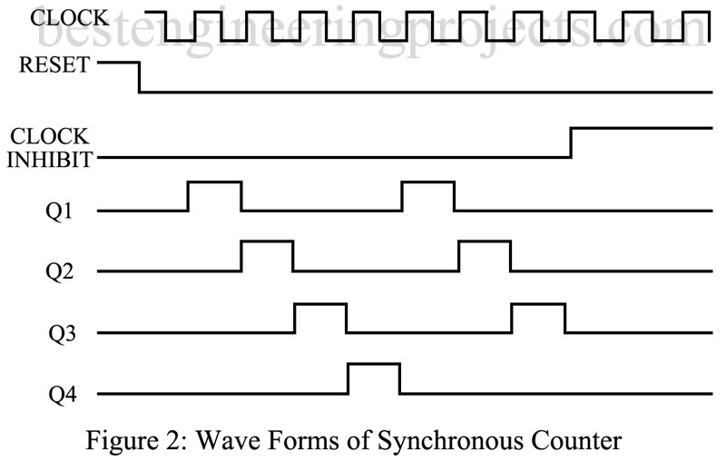
Synchronous counters are available in a large variety of sizes and with a number of standard output decoders. The essential features of this type of counter can be seen from the illustration of figure 1(a). Each of the flip-flops (FF) is controlled by the clock signal. Whatever data are entered must be entered in synchronism with the clock, because only when clock enables each FF can the counting or dividing operating take place. As indicated in the waveform diagram of figure 1(b), all the output signals, Q1 through Q4, have the same symmetrical pulse shape.
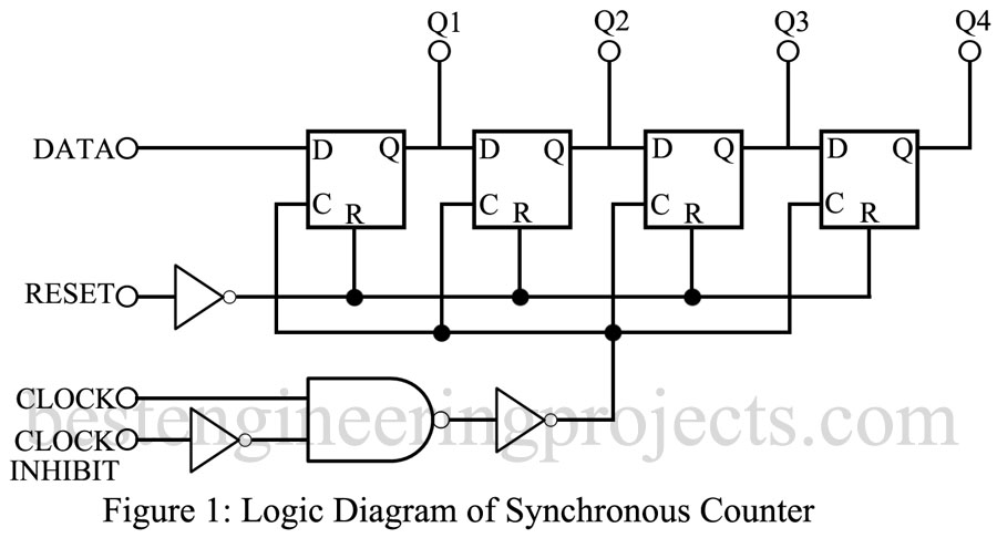
If we assume that the data input is the same as the clock signal, each output pulse will be the width of one complete square-wave cycle of the clock. Note that each output occurs one complete clock cycle after the previous one. The reset signal can be enabled at any time and, in the illustration of figure 1(a), it is kept at logic 0 after the start. The clock inhibit signal, however, has been set to logic 1 after seven clock cycles and all output signals remain at 0 thereafter. As indicates, the counter is advanced one count during each positive clock signal transaction, as long as the clock inhibit signal is at 0.
Key Parameters of Synchronous Counter IC SN74162
The electrical characteristics are essentially the same as those of a particular digital IC family.
- Maximum clock input frequency: Up to about 5.5 MHz for CMOS and 35 MHz for TTL devices.
- Clock pulse width: The maximum width of the clock input signal. This ranges from 60 to 200 ns for CMOS ICs and as low as 20 ns for TTL devices.
- Reset pulse width: The minimum width of the reset pulse. CMOS devices range from 60 to 30 ns, while TTL devices reset pulse widths are approximately 20 ns.
- Reset removal time: The minimum time required until the reset signal is removed and the counter operation is again enabled. A typical value for CMOS devices is 150 to 400 ns.
- Maximum power dissipation: in some instances, stated for the total package, in other per output stage. For CMOS a typical value is 500 mW from -40 to +600 TTL ICs are available with power dissipation of 100 mW for up to six output stages.
Applications
Synchronous counters are used in decade and binary computer control and timing circuits, for decade counters in clock displays, divide-by-N counting, and for frequency division.
Representative Part Number: Texas Instruments SN74162.
Comments
Most commercially available synchronous counters include additional gating and decoding circuits, making their logic diagram more complex than that presented in figure 1.