The essential function in all counter or divider IC is performed by the basic flip-flop (FF) which changes states only on either a positive or a negative going transaction. If a pulse or square-wave signal is applied to the input of an FF with positive logic, it will change state only on the rising edge of the signal. For every two pulses or square waves at the input, only one square wave will be available at the output. Every FF has a Q and Q bar output, one being the complement of the other.
Description of Counter or Divider IC
The term counter implies that pulses or square waves are counted, and this function is provided by adding logic gates to the basic FF configuration. The term divider more accurately describes the function of the FFs themselves since each FF stage divides the input frequency by two. In some applications the input frequency is divided by the series of FFs into another frequency that is a predetermined fraction of the input. In other applications the pulses applied to the input are counted and a logic output signal is generated when a previously specified number of pulses has passed through the counter. Because both counting and division can be performed by all devices described in this section, we will, from now on, use only the term counter.
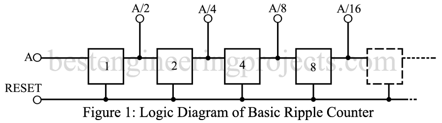
A basic “ripple” counter is illustrated in the logic diagram of figure 1. A square-wave signal is supplied at input A and A/2 appears at the Q output terminal of FF1. As illustrated, each stage divides its input frequency by two. The FFs are numbered according to the binary system. Note that FF1 operates at half of the input of frequency, while FFs will operate at 1/16 of the input frequency. If the output of the fourth stage (FF8) were connected to the reset line, this counter would count only the first 16 pulses. Once the sixteenth pulse has set FF8, the reset signal would prevent any further counting.
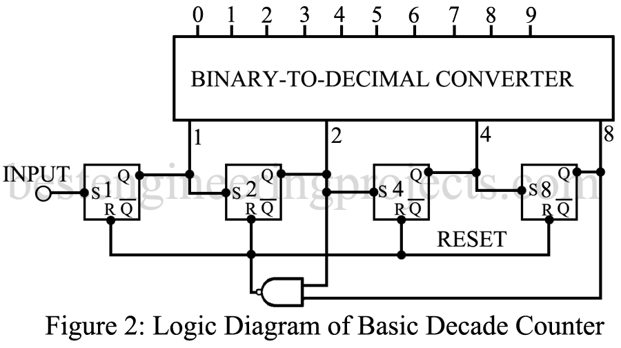
The logic diagram of 2 illustrated the minimum circuitry for a decade counter. Here, the NAND circuit senses the Q signal from FF2 and the Q signal from FF8. When both occur at the same time, the counter has counted a total of ten pulses of square waves and the reset line is activated. The four Q outputs will then represent the binary equivalent of the decimal number ten. During the first nine pulses which appears at the input, the binary equivalents of the corresponding decimal number will appear at the Q outputs, and these are converted to the decimal number 0 through 9.
Almost all of the counters described in the section are available with either straight binary or binary coded decimal (BCD) outputs. Counter are also available in two main categories, depending on the manner of operation. The basic ripple counter shown in figure 1 is considered asynchronous because it operates independently of a clock. It could be connected to a photocell that counts people passing through a gate. In this application it would count asynchronous events. In many digital logic applications, however, the counter operates under the control of the clock signal. This greatly reduces the chances of triggering by noise or other unwanted signals, but it also requires that the input signal by synchronized with the clock signal. In many synchronous counters the input and the clock are the same signal. Special features, such as programmable division by any number or up and down counting are available in both synchronous and asynchronous, binary to BCD counters. A wide variety of counters and special features is available in each of the different digital IC families.
Key parameters of Counter or Divider IC
The electrical characteristics are essentially those of the particular Counter or Divider IC family.
- Maximum operating frequency: This is the highest input frequency that a ripple (asynchronous) counter can accept. For synchronous counters this also determines the highest clock frequency. The maximum operating frequency depends, to some extent, on the digital IC family used. TTL counter have a higher operating frequency than CMOS types.
- Minimum input signal rise time: Unless a Schmitt-Trigger circuit is used in the input, slowly changing signals will not activate the counter. Sine waves and varying DC voltages are acceptable only when a Schmitt-Trigger input is used.
- Cascading: When several counter ICs are used in cascade, a carry-out signal from the last stage must be available as input for the next counter IC.
- Input Polarity: Indicates whether the FFs in the counter will change on positive (rising) or negative going (falling) edges.
- Available connections: on some counters the Q terminal of each FF is available, and in others some of the FF input circuits are also available. This permits the user to connect stages of the counter for a variety of applications. In some counters decoding circuitry is included, and only the fully decoded outputs are available.
- Noise characteristics: Indicate the relation of logic levels to noise signals. To some extent, this characteristic is dependent on the particular digital IC family.
- Output Load: In some counters, output driver circuits are included, while in others only a minimum output load-can be connected. To extent, output load capability depends on the particular digital IC family.
- Propagation delay: Normally stated as the time required from the input to the first Q terminal output. Total delays for the entire counter must be calculated, considering the number of states and the frequency division performed. The basic propagation delay time depends on the particular digital IC family.
- Control signal delay: The time required from the application of a particular control signal, such as reset, preset, up/down, until the control signal takes effect.
Applications
Counters are used for frequency division, as control timers, to drive time displays, as part of phase-locked loops, and in a host of other applications where either time or a number of events are being counted.
Comments:
The various types of counters described in this website not exhaust the full gamut of available counters. Special purpose counters, such as those used for digital clock radios, for color TV circuitry and other special applications, are also available.