In the article “Asynchronous Counter IC | SN74196”, we will discuss key parameters and applications of asynchronous counter IC SN74196. Let’s start with a description.
Description of Asynchronous Counter IC | SN74196
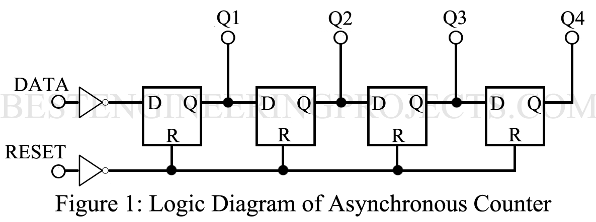
This type of counter can be accepting data that occur at any time. Whenever a new transition appears at the input, the effect of this change ripples down through the series of flip-flops (FF). Because there is no clock input to control the transition of each FF, an asynchronous counter is more subjected to ransom noise than the synchronous counter. The logic diagram of figure 1(a) illustrates the simplicity of a straight binary asynchronous counter. Only the data and reset inputs and an output from each FF are required.
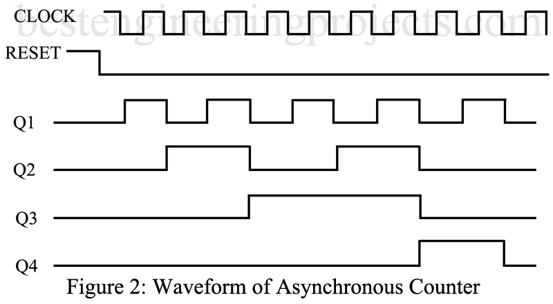
Assuming that the data is a square wave, illustrated in the waveform diagram of figure 1(b), and the reset line is at logic 0, the output of the four stages will “ripple” through, as illustrated. Note the frequency of Q1 is half of the frequency of the data input, Q2 is half of the frequency of Q1, Q3 is half of the frequency of Q2, etc. Because of the inverter connected to the data input, the first FF appears to trigger on the negative-going edge. When the reset signal changes from logic 0 to logic 1, all of the outputs are reset or 0.
Key Parameters
The electrical characteristics are essentially those of the particular digital IC family.
- Quiescent current: Total current drawn when the counter is not operating. 5.0 nA is typical at 5V for CMOS ICs.
- Maximum input frequency: 8 MHz is typical for CMOS, and up to 50 MHz is possible with TTL ICs.
- Input transition time: The very short rise and fall times of the input signal are limited by the maximum input signal frequency. Very long rise and fall times can be accommodated in those devices that have Schmitt-Trigger or similar hysteresis type input circuits. Many CMOS devices have no stated limits for this parameter.
- Reset pulses width: minimum value for COMS devices range from 250 to 500 ns. For TTL devices this will range from 50 to 100 ns.
- Reset removal time: This time is required after the reset has gone to logic 0 until the counter is operational again. For CMOS ICs, 150 to 250 ns is typical, while 20 to 100 ns is usually specified for TTL ICs.
Applications
Asynchronous counters are used for event counting, pulse counting in radioisotope detection applications, timing control, and similar applications. They are particularly useful in applications where the events to be counted or measured occur at random or pseudo-random intervals.
Representative Part Number: Texas Instrument SN74196
Comments
Most asynchronous counters are supplied with additional control and output logic circuits, making them more complex than indicated in the logic of Figure 1. Some manufacturers list them as ripple counters, while others classified them as asynchronous.