In this article we are going to learn what is tracking and floating voltage regulator with its key parameters, applications with appropriates comments. At first let’s see what about tracking voltage regulator.
Description of tracking voltage regulator
In effect, a tracking voltage regulator performs the function of two separate voltage regulators, positive and negative, with but a single adjustment to track both voltages accurately. As shown in figure 1, the voltage from either output to ground will remain the same regardless of load unbalance. Adjustment of the external potentiometer or resistive network will vary both positive and negative voltages in exactly the same way. Most tracking voltage regulators provide equal positive and negative voltages, but it is also possible to obtain tracking voltage regulator ICs for which the positive and negative voltages are different.
![]()
Key parameters of tracking voltage regulator
Essentially the same as for the fixed output or adjustable voltage regulator, except for the following:
Output voltage: The regulator output voltage maintained over the specified operating range. Typical value are  ,
,  ,
,  ,
,  .
.
Maximum power dissipation: Maximum power that the IC can dissipate at 250C (room temperature) without a heat sink or forced air cooling. Including both the positive and negative loads. Typical values range up to 3 watts.
Safe operation area (SOA): Combination of maximum output current and the difference between the input output voltage. Both positive and negative loads must be added to located the operating point within the safe operating are curve.
Applications of tracking voltage regulator
As a voltage regulated for power supplied required for op amps, bridge circuits, and other applications where positive and negative voltages must track each other.
Representative Part Number: Exar XR-4194.
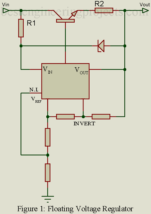
Description of Floating voltage regulator
Used for regulated voltages above 40 volts, the floating voltage regulated requires at least one external transistor, at least one zener diode, and several external resistors. As illustrated in the simplified diagram of figure 1, R1 limits the input current to the regulator IC. The reference voltage is applied to two resistive dividers. The tap from the grounded resistive divider is returned to the non-inverting input of an internal op amp, while the tap going from the reference voltage to the output voltage is connected to the inverting terminal of that op amp. One of these resistive dividers determines the output voltage, while the other sets the maximum output current. A positive voltage output floating regulator is shown, but the same principle applies to a negative floating voltage regulator. Additional external components are frequently used to protect the IC regulator against overvoltage and excessive output current.
Key Parameters of Floating Voltage Regulators
Essentially the same as for the adjustable voltage regulator of 1 except for the following.
Output voltage: The regulated output voltage maintained over the specified operating range. Because of the floating application, several hundred volts are often possible.
Input voltage-output voltage difference: Instead of absolute input voltage, this parameter limits the supplication of the floating voltage regulator. Typical difference voltages are in the order of 5 to 10 volts.
Applications of floating voltage regulator
To regulate the output of high-voltage power supplies, such as for photo multipliers and other vacuum tubes.
Representative Part Number: Exar XR-1543
Check out the article on floating charge circuit, Automatic battery float charger circuit
Comments
All of the tolerances and adjustment ranges are generally more limits for a floating voltage regulator and the manufacturers application notes should be carefully reviewed for the specific parameters and limitations.