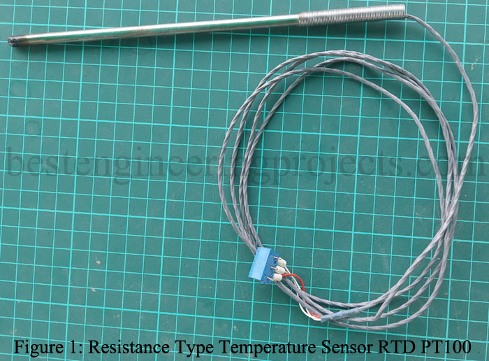
The article posted here is of Water Temperature Controller Circuit based on PT100. For temperature indication, a LED bar graph designed using 8-LEDs is used. PT100 is a temperature transducer that produces changes in impedance whenever the temperature changes. It has definite resistance at each temperature within its temperature range because it is made from temperature-sensitive elements. The reasons for using platinum type temperature transducers are cheap, high stability, and wide operating temperature range i.e. -1800C to 800C. Check out the article on Resistance Type Thermometer
PT100 is a probe type and is required to be kept immersed in the medium (say water) whose temperature is to be measured. Though PT100 has a wide measuring range of temperature, the circuit posted here is designed to respond between 300C to 1000C.
This water temperature controller circuit maintains the temperature at 1000C i.e. heater will be automatically on and increase the temperature of water till its temperature becomes 1000C. When the temperature of the water reaches 1000C, the heater will be turned off automatically.
Description of Water Temperature Controller Circuit
For a better description, Water Temperature Controller Circuit is divided into four different section
Temperature Sensing Circuit
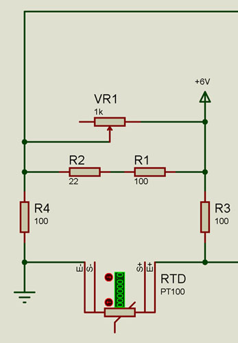
The temperature sensing element PT100 is connected as one arm of a Wheatstone bridge as shown in figure 2, where three resistors each of 100-ohm are connected as another arm. The reason for connecting the 100-ohm resistor is that the RTD PT100 has a resistance of 1000C at 00C (refer to datasheet). Some time resistance at 00C of RTD PT100 may not be 100-0hm, to address this issue a series resistance of 22-ohm is connected to one arm (opposite of PT100) of the Wheatstone bridge. A variable resistor of 1k is connected parallel to that arm to calibrate the PT100.
Figure 2: Wheatstone Bridge Connection
When the temperature is 00C, the resistance of PT100 becomes 100-ohm as a result the bridge becomes balanced. But when the temperature changes (say temperature increases) the bridge becomes imbalanced.
Instrumentation Amplifier
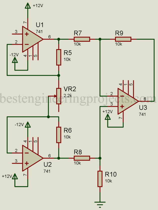
The output of the Wheatstone bridge is given to an instrumentation amplifier built using three op-amp IC 741 as shown in figure 3. The reason for using an instrumentation amplifier is the high stability of gain with a low-temperature coefficient.
Figure 3: Instrumentation Amplifier
The gain of this instrumentation amplifier can be calculated by using a formula.
Putting the value of resistor from figure 3, gain will be
This is the minimum gain of the instrumentation amplifier and can vary by varying variable resistor VR2.
Check out the article on Instrumentation amplifiers, their derivation, and their advantage.
This instrumentation amplifier generates 0V to 6V corresponding to the temperature 00C to 1000C.
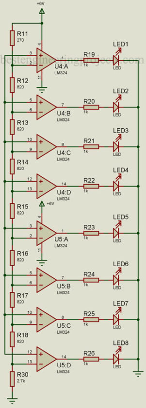
Comparator Circuit: The output of instrumentation is given to the comparator unit, shown in figure 4. This comparator circuit is built around two quad op-amp ICs LM324. Each LM324 IC contains four individual op-amp, thus the total comparator used in this circuit to show the temperature and further switch the heater and buzzer ON or OFF.
Figure 5: Comparator Circuit
The output of the instrumentation amplifier is connected to the non-inverting terminal of the comparator where the fixed reference voltage is connected to the inverting terminal. The output of the instrumentation amplifier is between 0V to 6V thus the reference voltage must not be more than 6V. Check out the article on comparator IC, its specification, and its applications.
Calculation of max. reference voltage
When the temperature is less than 300C no LED will glow, as soon as the temperature of the water reaches 300C LED8 starts to glow. With increasing temperature, LED8 through LED1 start glowing one after another with a difference of approximation of 100C. When the temperature of the water becomes 1000C all LEDs (LED8 to LED1) glow.
Switching Circuit
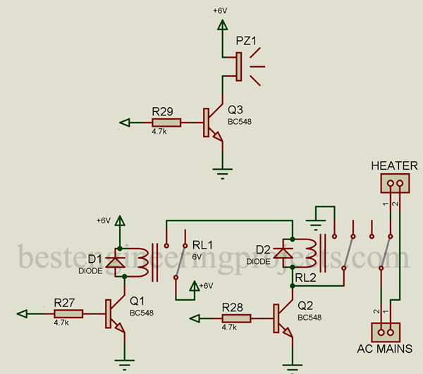
The switching circuit is designed using a general-purpose bipolar transistor as shown in figure 5. The output of the comparator drives these transistors which further drive the relay and buzzer. These relays are used to switch heaters ON and OFF.
Figure 5: Switching Circuit
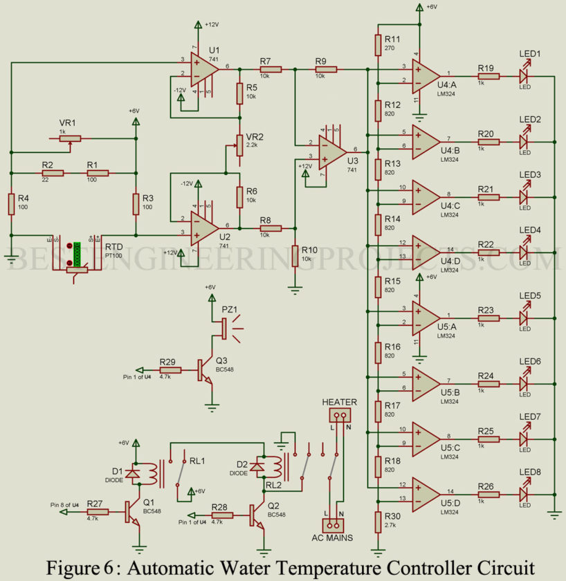
The complete circuit diagram of the water temperature controller is shown in figure 6.
Working of the Water Temperature Controller Circuit
Initially, PT100 senses the temperature by changing its resistance. This causes the Wheatstone bridge to be unbalanced and as a result, the voltage will appear at the input terminal of the instrumentation amplifier. This amplifier produces output voltage according to temperature. This output voltage is given to the comparator unit. This comparator unit reacts upon this input voltage by switching ON/OFF the relay and LEDs.
The heater is connected to the N/C of the relay, thus the heater will be ON initially. The heater starts heating the water when the temperature reaches 300C LED8 starts to glow. Gradually all the LEDs start to glow. When the temperature reaches 800C output of U4:C becomes high. This high output turns ON the relay driver transistor Q1 and as a result relay RL1 energizes. The power supply for the buzzer and heater driver relay is given through relay RL1.
When the temperature reaches 1000C output of U4:1 becomes high which further turns transistors Q2 and Q3 high. As a result, the buzzer started to sound and cut the supply of the heater.
Since the heater is OFF, the temperature of the water starts to decrease. As a result, the buzzer goes off. But the heater driving relay will be in the energized state due to the latching arrangement provided by its second pair of contacts as shown in the circuit diagram.
The heater will be ON again when the temperature of the water goes below 800C. In this way, the water temperature can be maintained automatically.
Calibration:
- Connect all the components as shown in the circuit diagram
- Immerse the PT100 in ice water (00C) and adjust preset VR1 such that the Wheatstone bridge becomes balanced, this led to producing 0V at output of instrumentation amplifier (pin 6 of U3).
- Now, Immerse the PT100 in billing water (1000C) and adjust the variable resistor VR2 till the output of the instrumentation amplifier becomes 6V.
Component List
| Resistor (all ¼-watt, ± 5% Carbon) |
| R1, R3, R4 = 100Ω
R2 = 22Ω R5 – R10 = 10KΩ R11 = 270Ω R12 – R18 = 820Ω R19 – R26 = 1KΩ R27 – R29 = 4.7KΩ R30 = 2.7KΩ VR1 = 1KΩ VR2 = 2.2KΩ |
| Semiconductors |
| U1 – U3 = LM741 (General purpose op-amp)
U4, U5 = LM324 (Quad Op-Amp) Q1 – Q3 = BC548 (General Purpose Bipolar NPN Transistor) D1, D2 = 1N4007 (General Purpose Rectifier Diode) LED1 – LED8 = 5mm any color LED |
| Miscellaneous |
| RD PT100
PZ1 = 5V Buzzer RL1 = 6V, 100Ω SPDT Relay RL2 = 6V, 100Ω DPDT Relay Connector for AC mains and heater |
Give me some idea about solar project and CCTV installation
We will post in very near future please subscribe for update.
Please check out the project CCTV Switcher circuit using timer IC 555