Washing machines have been an important part of our daily life. But, the issues we have to deal with in a few months of using them make it more difficult. Previously, we had already posted the Automatic Washing Machine control circuit. It is because most of the washing machines have a single-phase motor incorporated in the system and the timing and direction of the motor are controlled by an external mechanical switch which gets worn out so easily and is not economical on the other hand. And, the project “Motor Controller Circuit for Washing Machine” corrects that flaw in the conventional washing machine system that employs a single-phase motor.
Description of Motor Controller Circuit for Washing Machine
Figure 1 depicts the overall figure of the project. The single-phase motor work along with a master timer and a spin direction controller to calculate the washing time i.e. the period for which the motor should rotate and stop the motion of the motor after every 10 seconds for a 3-second interval and reverse the direction of rotation of the motor.
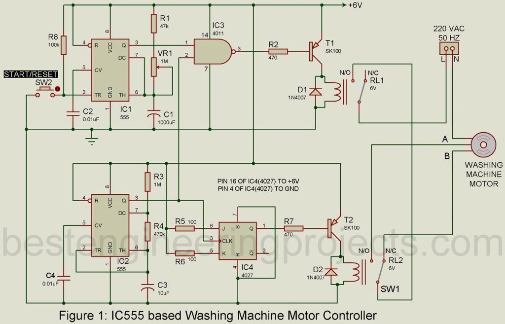
Fig. 2 shows the clear detailed way to control the rotation of the motor in the desired direction. For the motor to rotate in a clockwise direction as shown in fig 2(a), the switch SW1 should be in position A, and then the direct current flows through the coil L1 of the motor and due to capacitor C, current with a phase shift flows through the coil L2 of the motor. When the switch is switched to position B, vice-versa happens and thus the motor rotates in the anti-clockwise direction as illustrated in figure 2(b).
Though we can use the switch to change the direction of rotation of the motor, it can’t be done in an instant. It is best to wait for some time to change the direction of the motor to avoid any possible damage to the circuit. And, hence we have included IC2 (IC 555) to monitor the spin duration of the motor, it delivers on and off time pulses of ’10’ and ‘3’ seconds alternately at its output pins. This results in the washing machine automatically stopping for 3 seconds after every 10 seconds of rotation in either direction. Resistors R3 and R4 have adjusted accordingly for the project.

Master Time Section | Motor Controller Circuit for Washing Machine
For the master timer section required for the single-phase motor, IC1 (IC 555) is employed, and using a 1 mega-ohm potentiometer, we can set the time for which the motor should rotate. To avoid the on time, drop to 0 seconds when the knob of the potentiometer is in zero position, a 47-kilo-ohm resistor is placed in series next to the potentiometer.
The output of both ICs; IC1 and IC2 should be combined to stop the rotation of the motor as set by the master timer which is 18 minutes for the component values given in the project. For this purpose, a NAND gate N1(IC3) is incorporated into the circuit. The outputs obtained from both ICs; IC1 and IC2 are supplied as inputs to the gate which provides low output only when it receives high inputs from both ICs. A relay RL1 is attached at the end of pin 3 of the NAND gate through a PNP transistor T1. The low output from the NAND gate energizes the relay. The mains line 220V is taken through the relay RL1 and soon after 10 seconds is completed, the monitor turns off for 3 seconds. The time graph of the project is given in figure 3.

When IC2 is at ‘on’ time, the relay RL2 is energized by the low output provided by the negative-edge triggered JK flip-flop fixed at pin 2 of the IC2, then the washing machine motor starts to rotate in one particular direction. And, during the off-time of IC2, the N1 gate supplies high output which de-energizes relay RL1, and then it interrupts the flow of mains supply to RL2, and the monitor stop rotating.
Another resistor R8 holds pin 2 high and prevents floating-point trouble at trigger pin 2 of IC1.
PARTS LIST OF MOTOR CONTROLLER CIRCUIT FOR WASHING MACHINE
| Resistors (all ¼-watt, ± 5% Carbon) |
| R1 = 47 KΩ
R2, R7 = 470 Ω R3 = 1 MΩ R4 = 470 KΩ R5, R6 = 100 Ω R8 = 100 KΩ VR1 = 1 MΩ POT. |
| Capacitors |
| C1 = 1000 µF/16V (Electrolytic Capacitor)
C2, C4 = 0.01 µF (Ceramic Disc) C3 = 10 µF/16V (Electrolytic Capacitor) |
| Semiconductors |
| IC1, IC2 = NE555 (Single Precision Timer IC)
IC3 = CD4011 (CMOS Quad 2-input NAND Gate) IC4 = CD4027 (CMOS Dual J-KMaster-Slave Flip-Flop) T1, T2 = SK100 (General Purpose, medium Power PNP Transistor) D1, D2 = 1N4007 (General Purpose Rectifier Diode) |
| Miscellaneous |
| RL1, RL2 = 6V, 100Ω 1C/O Relay
SW2 = Push-to-on Switch |