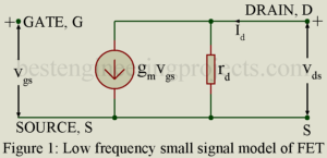
FET Parameter In a FET, instantaneous drain current iD is a function of (i) the instantaneous gate voltage VGS and (ii) instantaneous drain voltage VDS. Thus, ……..(1) Making use of equation 1, we may define the three FET parameter gm, rd and . Transconductance gm and Dynamic Drain Resistance rd Making Taylor series expansion of equation 1 and considering only the first two terms we get, ……..(2) Using the conventional small signal notation, , and may be put as, ……..(3) Where, …….(4) And, ……..(5) Parameter…
Read MoreArduino Controlled Variable Power Supply
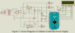
We all know that the power supply is the most basic unit of any electric/electronics circuit. The mostly electronic project, we have seen SLA batteries are often used, but they drain and we cannot get all-day performance. It is better to use the battery for backup rather than the main power supply. Another problem with using the battery is, when we draw high current constantly it becomes hot, it might create some serious issue, don’t think about this care? Don’t worry, the circuit Arduino Controlled Variable Power Supply is designed…
Read MoreJunction Field Effect Transistor (JFET) | Working
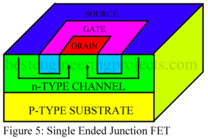
Introduction to Field Effect Transistor (FET) A Field Effect Transistor (FET) is a transistor in which current is controlled by an electric field. A conventional transistor is a bipolar device i.e. current is carried by two types of charge carriers namely electrons and holes. Hence a conventional transistor is referred to as a Bipolar Junction Transistor (BJT). An FET, on the other hand, is a unipolar device i.e. current is carried by only one types of charge carrier namely the majority carriers. What are the Advantage of Field Effect Transistor (FETs)…
Read MoreHigh Low Voltage Cutout Circuit
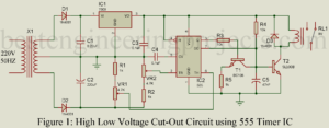
The protection of electrical and electronic appliances is the main concern these days. Some electronics appliance is very sensitive to voltage i.e. it only functions when adequate voltage is provided. Some appliances were even destroyed due to high and low voltage supply. To solve this type of issue we are posting a very simpler and more useful project called “High Low Voltage Cutout Circuit”. Previously we had already posted various types of appliance protecting circuits on bestengineeringprojects.com like: Auto Cut Circuit for Over and Under Voltage High Current Regulator Circuit…
Read MoreClass B Push Pull Amplifier
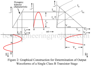
In class B push pull amplifier, output current (collector current) flows for only half the cycle of the input signal. Hence distortion is excessive. Single ended operation is, therefore, not possible in class B audio amplifier. Class B audio (un-tuned) amplifier must necessarily use push pull operation to reduce distortion. In effect, in class B push pull amplifier, one transistor say Q1 conduct during one half cycle while the other transistor namely Q2 conducts during the other half cycle. Class A power amplifiers may use either single ended or push…
Read MoreBlown Fuse Indicator circuit
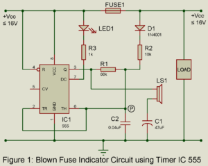
Blown fuse indicator circuit of the kind described here provides an ideal solution in such case. It indicates whether fuse is good or blown by generating audio alarm and glowing LED. Circuit Description and Working of Blown Fuse Indicator This circuit is based on 555 timer wired as an astable multivibrator. When the fuse is not blown, positive voltage is applied at junction P (IC’s pins 2 and 6) through R2 and D1. This holds the voltage at the junction above 2/3 Vcc and prevents the IC from oscillating. When…
Read MorePushpull Amplifier | Merits of Pushpull Operation
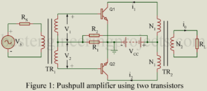
In a power amplifier using only one transistor, referred to as single ended amplifier, in spite of all care in design and operation, appreciable distortion results due to non-linearity of transfer characteristics. Such a distortion may be greatly reduced by using pushpull operation employing two transistors in a single stage as shown in figure 1. In the pushpull amplifier, the input signal is applied to the input of the two transistors through a centre tapped transformer TR1. Then the voltages V1 and V2 across the two halves of the center…
Read MoreArduino GPS Digital Clock
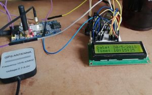
GPS (Global Positioning System) is getting more popular these days because of its application and uses in electronic project. Today, we are going to build a digital cock solely based on GPS module. The project “Arduino GPS Digital Clock” collects information from the satellite in the form of 70-character long string and show only date and time. In this article we will show you how to extract exact date and time from the string ($GPRMC) that received by GPS Module. Components used in Arduino GPS Digital Clock Arduino UNO Board…
Read MoreNegative Feedback Amplifier Circuit | Merits
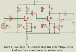
Negative feedback, no doubt, reduces the gain of an amplifier. Despite this drawback, negative feedback is popularly used in amplifiers because of its various merits discussed below. Stability of Gain Negative feedback results in increased stability of gain of the amplifier despite variations in the values of circuit components and device (BJT and FET) parameters caused due to such factors as temperature change, aging, replacement of circuit components, and supply voltage variation. Consider the feedback equation: Usually we keep . Then the feedback equation reduces to the following form: …
Read MoreSelf Resetting LDR Alarm using Timer IC 555
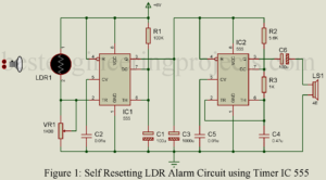
One of the most common projects made in electronics is burglar alarm or security alarm. If your search over the internet there are dozen of burglar or security alarms but the problem with this circuit is, it does not have a self-resetting option i.e. continuously sounds till someone switches off the system. Thus, in order to solve this type of problem (self-resetting) we have come with the project Self Resetting LDR Alarm using Timer IC 555. This circuit detects the interruption of light and produces sound for a definite interval…
Read More