We all know that the power supply is the most basic unit of any electric/electronics circuit. The mostly electronic project, we have seen SLA batteries are often used, but they drain and we cannot get all-day performance. It is better to use the battery for backup rather than the main power supply. Another problem with using the battery is, when we draw high current constantly it becomes hot, it might create some serious issue, don’t think about this care? Don’t worry, the circuit Arduino Controlled Variable Power Supply is designed carefully and it also includes solutions to the effects of battery drain.
Here we will discuss the construction detail and area where this project is applicable. The project Arduino Controlled Variable Power Supply is designed to deliver regulated 1.5V DC to 24V DC up to a maximum current of 3 Amp. We are also using two dedicated connectors for constant 24 V Dc and 12V DC.
Application of Arduino Controlled Variable Power Supply
- Need for constant current source for a long period
- Need for different voltage sources at a time.
- Ideal for high current and motors like servo motors or PMDC motors.
Special features of Arduino Controlled Variable Power Supply are – visual indication of output voltage in LCD.
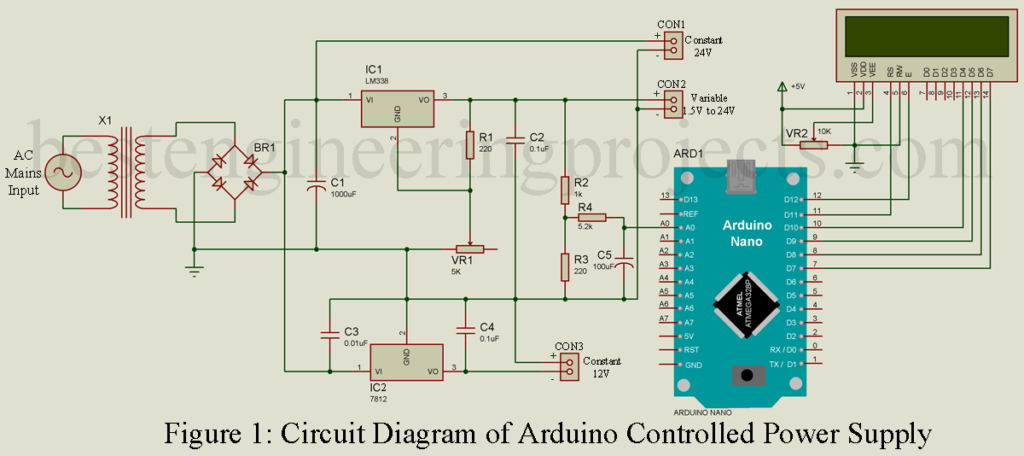
Circuit Description of Arduino Controlled Variable Power Supply
The circuit of Arduino Controlled Variable Power Supply is fabricated around a constant voltage regulator IC and high current adjustable voltage regulator. Arduino and LCD are used to indicate the output voltage of the circuit. The entire layout of the circuit of Arduino Controlled Variable Power Supply is illustrated in figure 1.
For a better understanding of circuits and working, we are dividing the entire circuit into four distinct sections.
Rectifier Unit | Arduino Controlled Variable Power Supply
A transformer is a static piece of the metallic box with the help of this we can step down the mains voltage at the same output power. The primary winding of the transformer is connected to AC mains where two terminals of the secondary winding are 24V AC and 0V. These two, winding are connected to the AC input terminal of the bridge rectifier (the Cathode of one diode is connected to the anode of another diode). The pulsating DC output is obtained from the output terminal of the bridge rectifier (the anode of one diode is connected to the anode of another diode and the cathode of one diode is connected to the cathode of another diode). Capacitor C1 filters the pulsating part of DC and smoothens the wave.
Constant Voltage Regulator Unit | Arduino Controlled Variable Power Supply
The two constant voltages i.e. + 12V and + 24V are obtained at CON3 and CON1 respectively. +24V DC is directly obtained from the positive terminal of capacitor C1 shown in the circuit diagram. Similarly, one output of the bridge rectifier is also connected to the Vin pin of a constant 12V series voltage regulator IC (IC2). As a result, regulated positive 12V is obtained at pin 3 IC2. In this way, we can obtain constant 12V and 24V output.
Variable output voltage | Arduino Controlled Variable Power Supply
The variable regulated power supply is designed around high current variable voltage LM338K. The output voltage of this voltage regulator is independent of the input voltage, it is purely dependent upon the resistor connected between the output pin, adjustment pin, and ground. We are using this voltage regulator as a variable power supply thus, we have to use a variable resistor. The formula involved for calculating the output voltage is given below

For our circuit arrangement, the value of resistor R1 and R2 are
R1 = 220
R2 = 5 K (Variable resistor)
From the datasheet of LM338, we found that IADJ must be in the range of 45 uM to 100uA (Depending upon the operating temperature).
If we adjust VR1 to its center say at 2.5K then output voltage will be


The value of the different parameters is fixed i.e. IADJ and resistor R1, thus, we can vary output voltage by adjusting the variable resistor. More the resistance of VR2 more the voltage.
NOTE: A capacitor value of 0.1 uF is needed at the input terminal of LM338 if the device (LM338) is more than 6 inches from the filter capacitor.
Check out other power supply circuits posted on bestengineeringprojects.com
- Adjustable Ripple-Regulated Power Supply Using 741
- Variable Switching Power Supply
- Universal Digital Power Supply Circuit
- Stabilized Power Supply With Short-Circuit Indication
- Short Proof Variable Power Supply
- Adjustable Bipolar Voltage Regulator Circuit Using LM337
- Self Switching-off Power Supply
- Dual Polarity 5v from 9v Battery
- 3.7V to 5V, 5.3V, and 6V Converter Circuit
Indicator Circuit | Arduino Controlled Variable Power Supply
The indicator circuit is designed around Arduino nano and a 16×2 display. The variable DC voltage is given to the analog pin of Arduino A0 through a low-pass RC filter. The purpose of using a low pass filter is, that the response of Arduino is not in real-time due to the noise present. Further, it converts it into a digital value. The 16×2 LCD does the task of displaying the output voltage. For this project, we are using a 4-bit mode LCD operation.
Software Code | Arduino Controlled Variable Power Supply
The software code of Arduino controlled variable power supply is written in Arduino programming language and compiled using Arduino IDE. The software code is very simple, it took analog input converts it into a digital value, and displays the result on an LCD. You can directly download the code from below and use it in your project, no need for further modification.
|
1 2 3 4 5 6 7 8 9 10 11 12 13 14 15 16 17 18 19 20 21 22 23 24 25 26 27 28 29 30 31 |
#include <LiquidCrystal.h> LiquidCrystal lcd(7, 8, 9, 10, 11, 12); int voltage; void setup() { Serial.begin(9600); // set up the LCD's number of columns and rows: lcd.begin(16, 2); // Print a message to the LCD. lcd.setCursor(0, 0); lcd.print("ArduinoPwrSupply"); lcd.setCursor(0, 1); lcd.print("Best Eng Project"); delay(2000); lcd.clear(); lcd.setCursor(0, 0); lcd.print("Voltage = "); } void loop() { int Analog1 = analogRead(A0); voltage = map(A1,0,1024,0,22); Serial.println(voltage); lcd.setCursor(10,0); lcd.print(voltage); delay(1000); } |
PARTS LIST OF ARDUINO CONTROLLED VARIABLE POWER SUPPLY
| Resistors (all ¼-watt, ± 5% Carbon else Specified) |
| R1, R3 = 220 Ω
R2 = 1 KΩ R4 = 5.2 KΩ VR1 = 5 KΩ VR2 = 10 KΩ |
| Capacitors |
| C1 = 1000 µF, 32V (Electrolytic Capacitor)
C2, C4 = 0.1 µF (Ceramic Disc) C3 = 0.01 µF (Ceramic Disc) C5 = 100 µF, 32V (Electrolytic Capacitor) |
| Semiconductors |
| IC1 = LM338 (5 Ampere variable voltage regulator IC, metal can package)
IC2 = LM7812 (12V Series voltage regulator) BR1 = Bridge rectifier, 6A Arduino NANO Board |
| Miscellaneous |
| X1 = 220V AC to 24V-0V, 5 Amp. Secondary transformer
16×2 Alphanumeric Display CON1, CON2, CON3 = 2 pin connector |