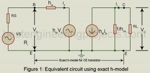
Approximate h-model: In the analysis of the transistor amplifier, we have as far used the exact h-model for the transistor. In practice, we may conveniently use an approximately h-model for the transistor which introduces an error of < 10% in most cases. This much error may be conveniently tolerated since the h-parameters themselves are not steady but vary considerably for the same type of transistor. We first derive this approximate CE h-model. Figure 1 gives the equivalent circuit of the CE amplifier using the exact h-model for the CE transistor.…
Read MoreCategory: Electronic Tutorial
Comparison of CE, CB and CC Configurations
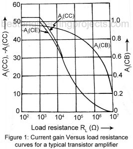
Comparison of CE, CB and CC Configurations: It is useful to study the variation of AI, AV and Ri with change in load resistance RL for each of the three configurations. Similarly, we may study variation of R0 with change of source resistance RS. Figure 1, 2 and 3 plots for each of the three configurations, current gain AI, voltage gain AV and input resistance Ri respectively as function of load resistance RL for the typically transistor whose h-parameters are given in Table 4.1. From these curves we get the…
Read MoreCommon Collector Amplifier or the Emitter Follower
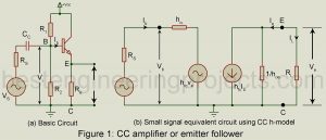
Common Collector Amplifier or the Emitter Follower: Figure 1(a) gives the basic circuit of a common collector amplifier, popularly called emitter follower. Its voltage gain is close to unity (one) and, therefore, any increment in the input voltage i.e. the base voltage appears as an equal increment in the output voltage across the load resistor in the emitter circuit. Thus, the emitter may be said to follow the input signal and hence the name emitter follower. The input resistance Ri of a CC amplifier or emitter follower is very high,…
Read MoreAnalysis of Common Base Amplifier (CB) using h-parameter
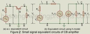
Analysis of Common Base Amplifier (CB) using h-parameter: Figure 1 gives the basic circuit of a transistor (NPN type) used as a common base (CB) amplifier. In this case, Vs is the signal voltage, Vi is the actual voltage at the input terminals and V0 is the output voltage. Figure 2(a) gives the a.c. equivalent circuit obtained on having removed the dc source. On replacing the CB transistor with its small-signal two generator h-parameter model we get the equivalent circuit of figure 1(b). Here also we assume sinusoidal input. Hence…
Read MoreAnalysis of Common Emitter Amplifier using h-parameters
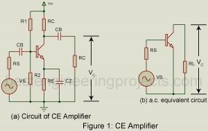
Analysis of Common Emitter Amplifier using H Parameter Figure 1(a) shows the circuit of a common emitter (CE) amplifier using self-bias and load resistor R0 capacitively coupled to the collector. Figure 1(b) gives the a.c. equivalent circuit. Here we have eliminated the biasing circuit consisting of R1, R2, Re, and Cz. The R1 – R2 combination is equivalent to resistance Rb (= R1 || R2) between base and ground. It is assumed that Rb is large in comparison with the input resistance of the amplifier between base and ground and…
Read Moreh-parameter Model for Transistor
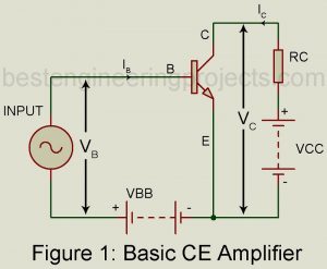
Transistor static characteristics curves are nonlinear. But for small signal operation, the point of operation moves about the quiescent operating point over a small range. Then the transistor parameters may be considered to be constant over this small range of operation. Derivation of h-Parameter model for transistor To drive the h-parameter model for a transistor, we consider the basic CE amplifier circuit of figure 1. The variable iB, iC, vB (=vBE) and vC(vCE) represent the instantaneous total values of currents and voltages. The input current iB and output voltage vC…
Read MoreCommon Emitter (CE) Amplifier | Operating Point
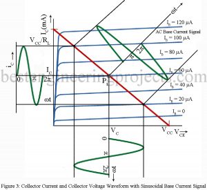
The Operating Point of Common Emitter Amplifier From the study of transistor characteristics, we find that amplification by transistor amplifier is most linear when the transistor operates in its active region. Hence the operating point must be suitably placed in the middle of the active region by suitable selection of external energy associated biasing circuit. Circuit Description of Common Emitter (CE) Amplifier Figure 1 gives the basic circuit of CE amplifier using NPN transistor bias through use of resistor Rb. Here capacitor Cb1, acts as the coupling capacitor to couple the…
Read MoreAudio Oscillators
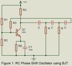
RC oscillators are principally used for generating audio frequencies. Two popularly used RC oscillators are (i) RC phase shift oscillator using either BJT or FET and (ii) Wien Bridge oscillator. Another popularly used audio oscillator is the Beat Frequency Oscillator (BFO). We here consider these three audio oscillators. RC Phase Shift Oscillator using BJT. Figure 1 gives the basic circuit. It is a sinewave feedback oscillator and uses an amplifier followed by three section R-C phase shift network. Output of the last section is fed to the base. We assume…
Read MoreSinewave Feedback L-C Oscillators
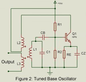
Popular sinewave feedback L-C tuned oscillators are listed below. These are principally used for generating RF oscillations. Tuned Collector Oscillator Tuned Based Oscillator Hartley Oscillation Colpitts Oscillator Clapp Oscillator Crystal Oscillator Tuned Collector Oscillator Figure 1 gives the basic circuit. A parallel tuned L-C circuit placed in the collector circuit constitutes the load impedance and determines the frequency of oscillation. The output voltage developed across the tuned circuit is inductively coupled to the basic circuit through the coil L2. The winding direction of the two coils L1 and L2 are…
Read MoreSchmitt Trigger | Circuit | Working
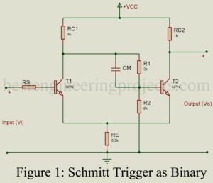
Fig 1 gives the schematic circuit of Schmitt trigger. It forms an important bistable multivibrator and differs from the basic Eccles-Jordon bistable multivibrator of Fig 1 in that (i) from output point C2 of T2 to the input of transistor T1 is missing and (ii) the feedback through resistor RE. Using transistors, the circuit is basically an emitter coupled binary. It is called Schmitt trigger after the name of the inventor of the vacuum tube Version. In this circuit, also there are two stable states. This results because of positive…
Read More