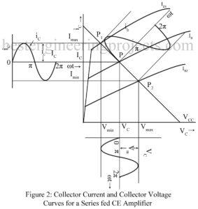
Large Signal Amplifier | Power Amplifier: In a multistage amplifier, first stage or the input stage and the intermediate stage are usually small signal class A amplifier stage while the last stage (the output stage) or sometimes last two stage are large signal amplifier (power amplifier) stage. Small signal amplifier stages serve to amplify the weak input signal to a sufficient large value to drive the final stage. The output stage generally feeds a transducer such as CR Tube, a loud speaker, a servo-control motor etc. the large signal amplifier…
Read MoreCategory: Electronic Tutorial
Transformer Coupled CE Amplifier
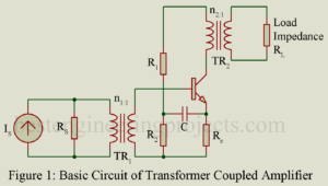
Figure 1 gives the basic circuit of a transformer coupled CE amplifier stage. In figure 1, a current source Is having shunt source resistance Rs drives the amplifier through a transformer TR1. Load resistance RL is fed from the collector output circuit through a transformer TR2. A transformer coupled CE amplifier finds following applications: As input stage of a multistage simplified and usually driven by a microphone. As output stage feeding the load impedance and As intermediate stage Transformer coupling permits impedance matching thereby resulting in greater power gain. The…
Read MoreAntilogarithmic Amplifier | Derivation
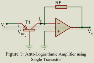
Antilogarithmic amplifier is one whose output is antilogarithmic (exponential) of input. Like logarithmic amplifier, antilogarithmic is also a non-linear amplifier. Antilogarithmic Amplifier using Single Transistor The circuit arrangement for Antilogarithmic amplifier is illustrated in figure 1. Here a general purpose NPN transistor is connected to inverting input of op-amp. A resistor is connected in feedback path. The output is depending upon output current of transistor and feedback resistor. Now for diagram, output voltage can be written as …..(1) Where, Is = Saturation current VT = Thermal Voltage As we…
Read MoreLogarithmic Amplifier using Diode and Transistor
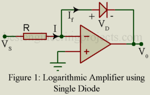
Logarithmic Amplifier using Diode and Transistor It produces output that is proportional to the logarithmic input It is a non-linear amplifier used for amplification or compression of a wide range of input signals for better resolution. It can be used direct DB display on a spectrum analyzer. You may also like: Antilogarithmic Amplifier Log Amplifier using a Single Diode and Op-Amp The circuit arrangement for the logarithmic amplifier/converter is illustrated in figure 1. Here a silicon diode D is connected in the feedback path and the current via the diode…
Read MoreInstrumentation Amplifier | Derivation | Advantage
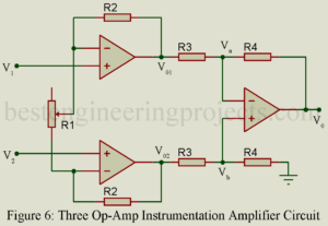
This article is all about instrumentation amplifier, its derivation, configuration, advantage and disadvantage. We had also try to describe different types of instrumentation amplifier like single op-amp based instrumentation amplifier, instrumentation amplifier using two and three op-amp. The electrical transducer low level output signal often require to be amplified before further processing and this task is usually get accomplish by use of instrumentation amplifier. There are several important characteristics of an instrumentation amplifier that set it apart from operational amplifier. Instrumentation amplifier have finite gain which is selectable within precise value…
Read MoreApplication of Op-Amp
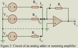
What are the application of op-amp (operational amplifier)? Op-Amp may perform numerous mathematical operations; hence the name operational amplifier. We here consider some of the applications of Op-Amp. Thus, consider the ideal inverting Op-Amp of figure 1 with voltage shunt feedback through Zf. Equation 1 may be used to secure various operations as analog inverter and paraphase amplifier, scale changer, phase shifter, analog adder, current-to-voltage converter etc. …..(1) Analog Inverter and Paraphase Amplifier: In Figure 1, Let Z1 = Zf, then AVf = -1 and V0 =…
Read MoreResistance Capacitance Coupled or R.C. Coupled Amplifier
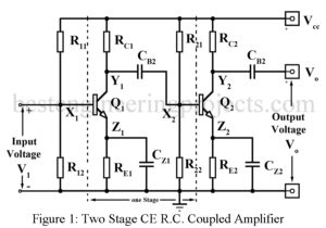
Resistance Capacitance Coupled or R.C. Coupled Amplifier Figure 1 gives the circuit of a two-stage common emitter R.C. coupled amplifier while figure 2 gives the circuit of a two-stage common source (CS) FET R.C. coupled amplifier. Typical component values are also indicated. In both amplifier circuits of Figure 1 and 2, X1 and Y1 are the input and output terminals of the first stage. The output at Y1 is coupled to the input X2 of the second stage through a coupling capacitor Cb2. This capacitor serves another function of blocking…
Read MoreInverting Operational Amplifier with Voltage Shunt Feedback
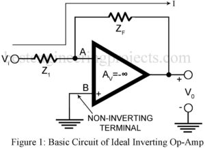
The ideal inverting operational amplifier with voltage shunt feedback from output terminal to the inverting input terminal feedback impedance Zf and with non-inverting terminal grounded configuration is shown is figure 1. 25+ verified electronics projects using op-amp 741. Description Inverting Operational Amplifier with Voltage Shunt Feedback This forms the basic inverting op-amp. It is “Inverting” because our signal input comes to the “-” input, and there has the opposite sign to the output. The feedback arrangement used here forms the voltage shunt feedback. Hence as per theory of feedback amplifiers,…
Read MoreCascading of Amplifier Stages
What is Cascading of Amplifier Stages? A single stage of amplifier can provide only a limited current gain or voltage gain. Most of the applications require much higher gain. Hence, we usually use several amplifier stages connected in cascade i.e. connected such that the output of one stage becomes the input to the next stage. Thus, a multistage amplifier or cascade amplifier may provide a higher voltage gain or current gain. Cascading of amplifier stages is usually done to increase the total gain of the amplifier. However, sometimes cascading is…
Read MoreClassification of Amplifiers
Amplifiers may be classified or Classification of Amplifiers in several ways as described below: According to the Frequency Range | Classification of Amplifiers Thus amplifiers may be classified as below: DC (Direct coupled) Amplifiers from zero frequency (dc) onwards. Audio Frequency Amplifiers 20 Hz to 20 KHz Video Frequency Amplifiers up-to a few MHz. Radio Frequency (RF) Amplifiers from a few KHz to hundreds of MHz. Ultra-high Frequency (UHF) and Microwave Amplifier up-to hundred or thousands of MHz. According to the method of operation | Classification of Amplifiers The position of the…
Read More