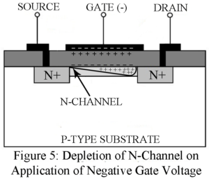
Metal Oxide Semiconductor FET (MOSFET) MOSFET is of greater commercial importance than the junction FET. Types of MOSFET Enhancement MOSFETs and Depletion MOSFETs. Enhancement Type MOSFET Figure 1 gives the cross-sectional view of a p-channel enhancement MOSFET. It consists of a lightly doped n-type substrate into which all diffused two highly dipped p + region spaced 10 to 20um apart. One region, say the left-hand region, acts as the source while the other region acts as the drain. A thin insulating layer of SiO2 of thickness 1000 to 2000 A…
Read MoreCategory: Electronic Tutorial
FET Parameter | Small Signal Models for FET
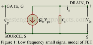
FET Parameter In a FET, instantaneous drain current iD is a function of (i) the instantaneous gate voltage VGS and (ii) instantaneous drain voltage VDS. Thus, ……..(1) Making use of equation 1, we may define the three FET parameter gm, rd and . Transconductance gm and Dynamic Drain Resistance rd Making Taylor series expansion of equation 1 and considering only the first two terms we get, ……..(2) Using the conventional small signal notation, , and may be put as, ……..(3) Where, …….(4) And, ……..(5) Parameter…
Read MoreJunction Field Effect Transistor (JFET) | Working
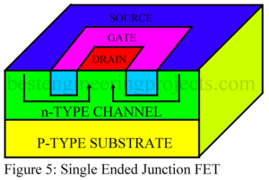
Introduction to Field Effect Transistor (FET) A Field Effect Transistor (FET) is a transistor in which current is controlled by an electric field. A conventional transistor is a bipolar device i.e. current is carried by two types of charge carriers namely electrons and holes. Hence a conventional transistor is referred to as a Bipolar Junction Transistor (BJT). An FET, on the other hand, is a unipolar device i.e. current is carried by only one types of charge carrier namely the majority carriers. What are the Advantage of Field Effect Transistor (FETs)…
Read MoreClass B Push Pull Amplifier
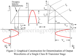
In class B push pull amplifier, output current (collector current) flows for only half the cycle of the input signal. Hence distortion is excessive. Single ended operation is, therefore, not possible in class B audio amplifier. Class B audio (un-tuned) amplifier must necessarily use push pull operation to reduce distortion. In effect, in class B push pull amplifier, one transistor say Q1 conduct during one half cycle while the other transistor namely Q2 conducts during the other half cycle. Class A power amplifiers may use either single ended or push…
Read MorePushpull Amplifier | Merits of Pushpull Operation
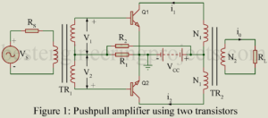
In a power amplifier using only one transistor, referred to as single ended amplifier, in spite of all care in design and operation, appreciable distortion results due to non-linearity of transfer characteristics. Such a distortion may be greatly reduced by using pushpull operation employing two transistors in a single stage as shown in figure 1. In the pushpull amplifier, the input signal is applied to the input of the two transistors through a centre tapped transformer TR1. Then the voltages V1 and V2 across the two halves of the center…
Read MoreNegative Feedback Amplifier Circuit | Merits
Negative feedback, no doubt, reduces the gain of an amplifier. Despite this drawback, negative feedback is popularly used in amplifiers because of its various merits discussed below. Stability of Gain Negative feedback results in increased stability of gain of the amplifier despite variations in the values of circuit components and device (BJT and FET) parameters caused due to such factors as temperature change, aging, replacement of circuit components, and supply voltage variation. Consider the feedback equation: Usually we keep . Then the feedback equation reduces to the following form: …
Read MoreFeedback in Amplifiers | Feedback Techniques
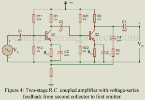
What is Feedback? What is Feedback in Amplifier? Feedback: Feedback is a phenomenon of universal importance and has, therefore, entered the general vocabulary. Thus, consider the following situation: you are an officer. You have instructed a subordinate to do a certain job. After some time, the person informs you about the state of job, whether satisfactorily completed or there are some difficulties. Thus, information constitutes the feedback. You definitely want this feedback to ensure that the job was been done; if not then what corrective measures are to be adopted.…
Read MoreMaximum Collector Efficiency of Class A Amplifier
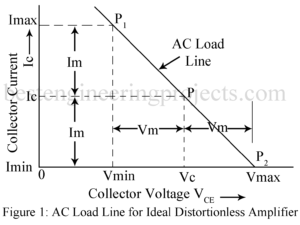
Maximum Collector Circuit Efficiency of Class A Amplifier Conversion Efficiency An amplifier draws a.c. power from dc supply (collector supply VCC in CE amplifier) and converts a part of it into useful a.c. power delivered to the load impedance. The ratio of the a.c. output power to the d.c. power from the supply source in the output is called the conversion efficiency, also called collector circuit efficiency in the case of CE amplifier and is denoted by Greek letter . Thus, ……(1) For present analysis, we assume a resistance…
Read MoreTransformer Coupled Audio Power Amplifier
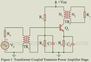
Transformer Coupled Audio Power Amplifier: Untuned large signal amplifier (power amplifier) of class AB and B type invariably use transformer coupled stages while those of class A type also generally use transformer coupled stage. RC coupled stages are not used because the quiescent current flawing through the load resistor results in large wastage of dc power in it. This dc power dissipated in the load resistor does not contribute to the useful ac output power. Further flow of dc current through the output device is not desirable. Hence it is…
Read MoreHarmonic Distortion in Amplifier
Second Harmonic Distortion in Amplifier In the graphical analysis given in the preceding article, the amplifying device is assumed to be preferable linear. Thus, we have assumed the output characteristics to be linear, parallel and equi-spaced for equal increments of the parameter. Then the corresponding dynamic transfer characteristic is also linear. Thus, linear amplification requires dynamic transfer characteristic to be linear. In practice, however, the dynamic transfer characteristic is never truly linear. For optimum linearity of amplification using the available amplifying device, we operate over such small region of dynamic…
Read More