Running lights effect is not a new idea for electronics hobbyist. But this multi-pattern running light becomes unique as four patterns can be selected. In the first pattern, out of eight lights, alternate light go ‘on’ and ‘off’. In the second pattern, two adjacent lights go ‘on’ and the following two go ‘off’. This pattern is shifted from left to right. In the third pattern, four adjacent lights go ‘on’ and these are sifted to right. In the fourth pattern all the eights light go ‘on’ and ‘off’ one by one from left to right. All the lights are of ordinary 230V bulbs controlled by triacs.
Circuit Description of Multi-Pattern Running Light
The heart of the circuit multi-pattern running light is a serial-in-parallel-out shift register IC 74164 (IC3). When clock pulses are applied at pin 8, for every clock pulse, output at pin 3 is sifted to pin 4 and output at pin 4 is sifted to pin 5 and so on, as per the logic state given at input pins 1 and 2.
An oscillator of multi-pattern running light is wired around IC1 NE555 and the square pulse are applied to IC2 (7493) and IC3 (74164). The frequency of oscillator can be varied with VR1.
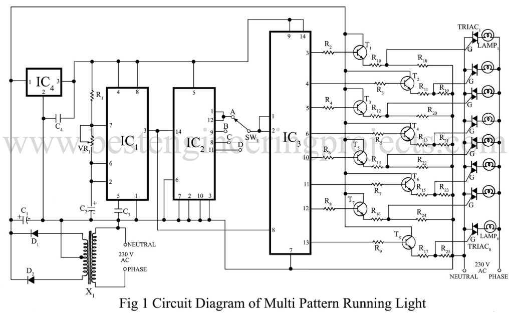
IC2 is divided by 16 counter and its output pins are 12, 9, 8, 11. By connecting these outputs through rotary switch to inputs of IC3, four different pattern can be selected as mentioned above.
Switching circuits of multi-pattern running light constitutes transistors and triacs. As output of IC3 cannot drive triacs directly, 8 transistors (BC148) are used for driving 8 triacs. Triacs of 4 Amps, 400 PIV (Peak Inverse Voltage) can handle 30 nos. of light.
PARTS LIST OF MULTI-PATTERN RUNNING LIGHT
|
Resistor (all ¼-watt, ± 5% Carbon) |
|
R1 = 22 KΩ R2 – R9 = 10 KΩ R10 – R17 = 100 Ω R18 – R25 = 100 KΩ VR1 = 100 KΩ |
|
Capacitors |
|
C1 = 1000 µF/16V (electrolytic capacitor) C2 = 10 µF/16V (electrolytic capacitor) C3, C4 = 0.01 µF (ceramic capacitor) |
|
Semiconductors |
|
IC1 = NE555 IC2 = 7493 IC3 = 74164 IC4 = 7805 T1 – T8 = BC148 D1, D2 = 1N4001 TRIAC1 – TRIAC8 = 4 AMP, 400 PIV |
|
Miscellaneous |
|
X1 = 230V AC Primary To 9V-0V-9V, 500mA Secondary Transformer SW1 = Single pole 4-way rotary switch LAMP1 – LAMP8 |