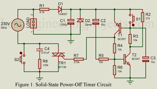
Ever left a device plugged in overnight, only to realize it’s been sipping power like a lazy vampire? We all have. Even when switched off, many devices still drink up energy, wasting precious electricity and silently adding to the bill. What if there was a smarter way? Well, guess what—there is! Today, we’re building a solid-state power-off timer circuit that not only cuts the load but consumes absolutely no energy when turned off. Why This Circuit is a Game-Changer You see, most circuits out there rely on relays or electromechanical…
Read MoreCategory: Basic Electronic Projects
Different electronic project for entry level which are easy to build and understand.
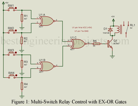
Multi-Switch Relay Control with EX-OR Gates
Many electronics enthusiasts love to design their custom control circuits. Today, we’re exploring an interesting circuit that accomplishes single relay control through multiple switches. This circuit accomplishes this achievement and introduces the utilization of EX-OR gates within control systems. Check out the article on “How to make relay switch circuit” Before we delve into the circuit’s details, let’s first understand what an EX-OR gate is. Exclusive OR Gate An exclusive OR gate, often abbreviated as EX-OR performs the following logic “The output of a 2-input Exclusive OR gate assumes the…
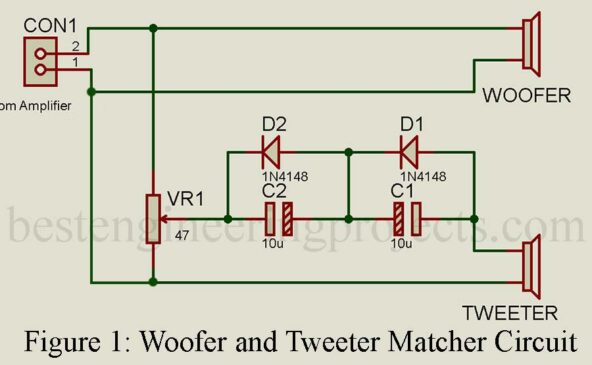
Read MoreOptimizing Speaker Performance with Woofer and Tweeter Matcher Circuit
Discover how a woofer and tweeter matcher circuit enhances audio systems by producing balanced sound. Learn how specialized components optimize low and high frequencies, leading to an enjoyable listening experience. Introduction: A speaker’s frequency response plays a crucial role in delivering high-quality sound across the audible spectrum. However, not all speakers can reproduce frequencies uniformly, leading to an imbalanced sound output. To overcome this challenge, audio systems incorporate specialized components known as woofers and tweeters, each optimized for handling specific frequency ranges. Woofer and Tweeter Function: Woofer: A woofer is…
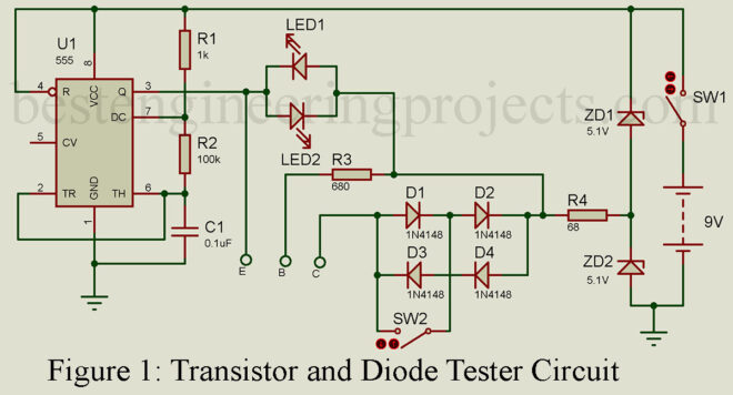
Read MoreTransistor and Diode Tester using 555 IC
Transistors and diodes are fundamental components in electronics and play a significant role in many circuit designs. When it comes to incorporating these active components into a circuit, it’s crucial to ensure that they are working correctly. Therefore, it’s essential to have a reliable method to test transistors and diodes. Circuit Description of Transistor and Diode Tester using 555 IC In this article, we will discuss a simple yet effective transistor and diode testing circuit that can help you identify whether these components are functioning correctly or not. The circuit…
Read MoreAC Mains Voltage Indicator Circuit
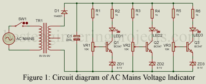
An AC mains voltage indicator circuit is a very useful device that indicates the different levels of the mains voltage. This circuit utilizes three different LEDs to indicate the different ranges of voltage i.e. Low, Nominal, and High. It is important to know this information when you are working with electrical equipment because it can help you ensure that everything is working properly and that you are not overloading the circuit. Fortunately, you don’t need to be an electrical expert to build an AC mains voltage indicator. In fact, even…
Read MoreHow to Make Relay Switch Circuit
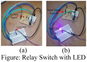
In this tutorial, you will learn how to make your relay switch circuit for Arduino in a few easy steps. We often see many electronics hobbyists especially Arduino users buy expensive relay modules instead of building their own. The general price of the relay module found in the market is about $2 but you can make your own for less than $0.70. In the tutorial Relay Switch circuit for Arduino, you will learn Relay and Operating principle Pin Identification of Relay Component value calculation and choosing the best for your…
Read MoreBlown Fuse Indicator circuit
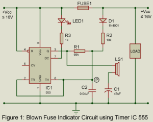
Blown fuse indicator circuit of the kind described here provides an ideal solution in such case. It indicates whether fuse is good or blown by generating audio alarm and glowing LED. Circuit Description and Working of Blown Fuse Indicator This circuit is based on 555 timer wired as an astable multivibrator. When the fuse is not blown, positive voltage is applied at junction P (IC’s pins 2 and 6) through R2 and D1. This holds the voltage at the junction above 2/3 Vcc and prevents the IC from oscillating. When…
Read MoreTouch Switch Circuit using Transistor
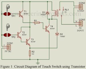
Today, I have come up with another simple but very applicable project ‘Touch Switch Circuit using Transistor’. With this simple project, you can modify your existing electrical/ electronic appliance with a modern touch facility. A few days earlier I bought a reading lamp from one of the Chinese stores, the design of the Chinese product is quite impressive. The thing that motivates me to write this post is touch facilities i.e. you can on and off the lamp by simply touching the touch plate. The circuit posted here used two…
Read MoreAutomatic Fence Lighting with Alarm
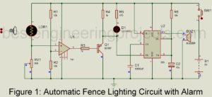
Today, in this article we are going to teach you how to make an automatic fence lighting circuit with an alarm using op-amp 741 and timer IC 555. Fence lighting is used for security purposes and can be used at various places like door alarms, pathway alarms, etc. where monitoring is required. Various types of fence lighting circuits are already available over the internet but the problem with that circuits is they required high precision alignment. To overcome this problem, we designed a very sensitive automatic fence lighting circuit. We…
Read MoreLaser Based Communication Link
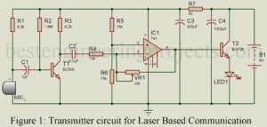
Communication is an essential part of our daily life. The project; “Laser-Based Communication Link” allows people at a distance of around 500 meters to communicate wirelessly through a laser. Various other laser-based projects posted on bestengineeringprojects.com are:- (a) Speech Communication using Laser (b) Mini Laser Turret (c) Laser Voice Transmitter Circuit The project unlike other wireless media uses laser light from the transmitter torch as a carrier instead of RF signals used in the conventional system. At the receiver end, the phototransistor should be aligned in a line of sight position…
Read More