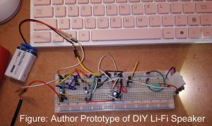
Here in the article I am going to show you “How to design DIY Li-Fi speaker” we are going to show you how to make Li-Fi speaker i.e. uses light to transfer data. This article consist of entire detail like design procedure, circuit diagram, and description. Introduction to Li-Fi (Light Fidelity) The term wireless has been gaining so much popularity in the recent years. Li-Fi is another block to growing platform. The term Li-Fi; Light Fidelity sounds somehow similar to Wi-Fi and they share a lot of common features. Both…
Read MoreCategory: Basic Electronic Projects
Different electronic project for entry level which are easy to build and understand.
Battery Status Indicator Circuit
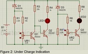
Here is a simple circuit using transistor called ‘Battery Status Indicator Circuit’ used to indicate two states of battery i.e. under charged and over charged. Previously, we had already posted similar circuit called Battery Voltage State Indicator using 741 used to indicate three states of battery i.e. charged, charging and discharge. Similarly, you can also design circuit which indicate status of battery in 10 different level. Circuit Description of Battery Status Indicator The circuit of Battery Status Indicator Capacitor is shown in figure 1. The main components of Battery State…
Read MoreAudio Signal Tracer Schematic
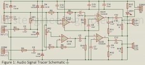
Signal transmission can be quite troublesome sometimes. To ensure that the signal is passed through a defined distance, here we have presented an “Audio Signal Tracer Schematic”. As mentioned in the title; ‘Audio Signal Tracer Schematic’, this project is implemented to troubleshoot audio signals transmission in electronic circuits and radio, etc. It comprises two loudspeakers being Audio Signal Tracer and is packaged into a small hand-held test probe. The only power source required by the circuit is a battery and thus is more useful. Amplitude-modulated signals can also be detected…
Read More10 Level Battery Charge Indicator Circuit
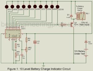
We already indicates state of battery using battery status indicator circuit and battery voltage state indicator using 741 IC, this time we indicate battery status in 10 different levels. The project “10 Level Battery Charge Indicator Circuit” is designed using comparator IC LM3914, used to indicates charge of battery in 10 different level. The project uses 10 LEDs to indicate the charge of battery in 10 level i.e. each glowing LED indicates 10% of charge in battery. Let say, if seven LEDs glow, the charge available in battery is 70%. It…
Read MoreDIY Light Detector Circuit using LED
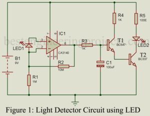
Today we come with a unique idea i.e. Photodiode using LED. This project utilized an LED to detect and respond to the presence and absence of light. Before starting the description and working of circuit DIY Light Detector Circuit using LED, we would like to describe a few electronics components. LED: Light-emitting diode is a photoelectric device that converts electrical energy into light energy. It is a heavily doped P-N junction diode that under forwarding bias emits spontaneous radiation. Photodiode: Photodiode is an optoelectronic device in which current carriers are…
Read MoreSolder Fumes Extractor Circuit
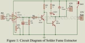
Solder Fumes Extractor Circuit: Soldering in electronics is analogous to fixing a component using glue. It is a general phenomenon in the field of electronics that involves fixing electronic components into a special board called PCB with the help of instruments like soldering iron and electrical solder commonly called ‘Solder wire’. While soldering we all face the problem of toxic fumes. These fumes are of lead solder wire and flux. Combinedly, these fumes are highly toxic if an excess amount is inhaled. To solve this problem, here we designed a…
Read MoreAutomatic Night Lamp Circuit
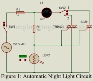
The project “Automatic Night Lamp Circuit” is very simple and built around four major components i.e. TRIAC, SCR, LDR, and Resistor. The lamp used in this project is a porch light that would turn on automatically in dark (nighttime) and turn off in light (daytime). Circuit Description of Automatic Night Lamp Circuit The circuit of Automatic Night Lamp Circuit is used shown in figure 1. The circuit is very simple and straightforward that anyone has very little knowledge about TRIAC and SCR. Silicon Controlled Rectifier | Automatic Night Lamp SCR…
Read More10-Channel Multiplexer Circuit using 555 IC
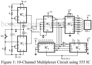
This project is a low-cost multiplexing system for ten channels. The project 10-channel multiplexer circuit using 555 IC can be used as an add-on device for a single point indicating system. Both auto and manual selection are incorporated with the visual indication of channel number. It is suitable for signals concerning a common line. However, for double-ended signals, the input LOW lines can be made common and the input High lines can be multiplexed. This can be used for thermocouple signals, strain gauges, and any other AC/DC signal in the…
Read MoreAlarm Circuit for Clocks
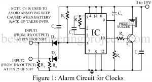
Here is an alarm circuits for clocks using IC 5387, 5316, LM8361 etc. (any IC giving an alarm and a 1Hz outputs). This circuit has the following advantages over most of other alarm circuits (especially alarm circuits based on IC 555): Working Principle of Alarm Circuit for Clocks The quiescent current is only 0.1 mA which is much less than the 10-15 mA consumed by 555 circuits. Hence the life of 9V battery is increased by above three times. The operation current is also very small. IC 555 based circuitry consumes…
Read MoreSound Level Meter Circuit
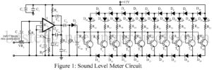
The project sound level meter circuit shown here comprises a display circuit for 10-segment resolution i.e. used to indicate sound level up to 10 levels. Recording of sound in the studio involves critical adjustment of recording levels and level of bias current. If the level of sound is very much it may cause some distortion while a low level of sound reduces the SNR (Signal to Noise Ratio) as a result the sound may be too noisy. Care should be taken while recording sound to regulate the signal so that…
Read More