Automatic Solder Smoke Extractor: Soldering is the process of joining electric/electronic components together. It is a very basic and most used process in the field of electronics because it is used to establish a secure connection between PCB and the components. Multiple types of solder wire are available at the market varying in dimensions and quality. Although there are multiple types of solder wires almost all of them are made from Lead and tin.
Only the heated iron melts the wire so it is a must to let the iron heat up completely. When solder wire melts, smoke comes out. This smoke is toxic because it is a combination of lead and flux. Inhaling these smokes may cause health issues. In order to remove this smoke, we have designed an automatic smoke extract circuit that automatically extracts the poisonous smoke from the workplace.
Components required for Automatic Solder Smoke Extractor
| Resistors (all ¼-watt, ± 5% Carbon) |
| R1, R5 = 1KΩ
R2, R6 = 470Ω R3 = 10KΩ R4 = 4.7MΩ VR1 = 470KΩ |
| Capacitors |
| C1 = 100nF (Ceramic Capacitors)
C2 = 10nF (Ceramic Capacitors) C3 = 1µF, 25V (Electrolytic Capacitor) |
| Semiconductors |
| IC1 = uA741 (General purpose operational amplifier)
IC2 = LM555 (Timer IC) Q1 = SL100 or any other power transistor D1 = 1N4001 (Rectifier Diode) LED1 = 5mm Red color LED LED2 = 5mm Green color LED |
| Miscellaneous |
| RT1 = 5.5K NTC Thermistor
FAN = 12V DC Fan Heat sink for transistor |
Advantages of Automatic Solder Smoke Extractor
- Simple and easy understandable circuit.
- Cheap and made from easily available components.
- Automatic and adjustable
Working Principle of Automatic Solder Smoke Extractor
The arrangement of this device is done so that the soldering iron must be kept close to the thermistor.
Case 1: When the soldering iron is at the station thermistor becomes hot and the output of the comparator becomes high. The high output of the comparator does not trigger time IC and the exhaust fan will remain off.
Case 2: When the soldering iron removes from the station, the thermistor starts to cool down and its resistance starts to increase. This increase in resistance will lower the voltage at the comparator non-inverting terminal and subsequently change the output from high to low. The Low output from the comparator triggers the timer IC 555 (IC2) for approx 30 seconds. As a result, switching transistor Q1 starts to conduct and switch ON the fan for approx 30 seconds.
This phenomenon continues.
Circuit Description
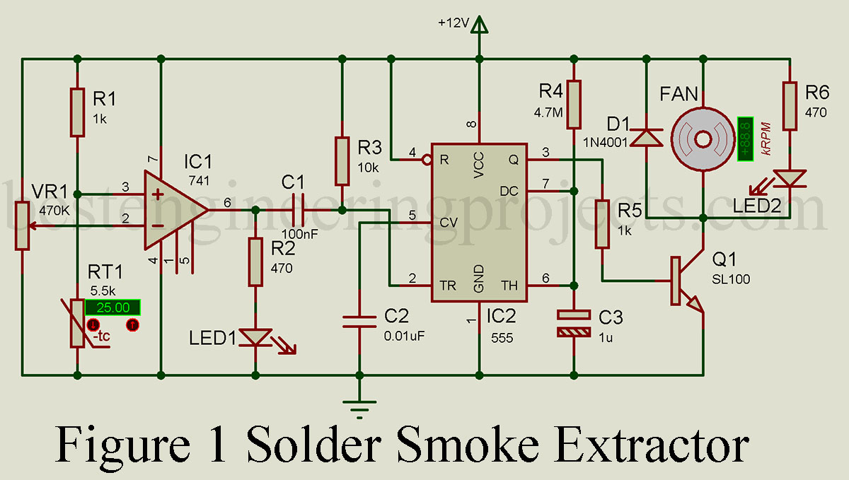
The circuit of the solder smoke extractor is shown in figure 2. The circuit has four different sections i.e.
- Temperature sensing section
- Comparator section
- Timer section
- Switching section
Temperature sensing section
The temperature sensing section is designed around a 5.5K NTC thermistor. The NTC is a passive resistance variation type temperature sensor whose resistance change according to changes in temperature. When temperature increases its resistance decreases and vice versa. A series voltage divider network is designed using a 10K resistor (R1) and a thermistor (RT1). The output of this voltage divider network is connected to the non-inverting terminal of the comparator. When the temperature change, the resistance of the voltage divider network also change as a result the voltage at the non-inverting terminal also change.
Comparator Section:
The comparator section is built around op-amp 741 IC. A comparator compares two voltage levels connected to its input. A fixed reference voltage through a variable resistor VR1 is connected to its inverting terminal (pin 2) whereas the output of the voltage divider network made using a thermistor is connected to its non-inverting terminal (pin 3). Initially, the output of the thermistor is high because the non-inverting terminal voltage is more in comparison to inverting terminal. When the temperature increases the resistance of the thermistor decreases which lowers the voltage at the non-inverting terminal in comparison to inverting terminal. In this instance the output change from high to low. When the output of the comparator is high, LED1 start to glow indicating the exhaust fan is OFF.
Timer Section
The timer IC 555 is configured in monostable mode (i.e. timer mode). The output becomes high for a fixed interval of time and this time is determined by resistor R4 and capacitor C2. With this arrangement, the output becomes high for approx 30 seconds. Timer IC is a low-trigger device so, when the output of the comparator IC changes from high to low it gets triggered. Resistor R3 of 10K is used as a pull-up resistor which pulls Pin 2 of timer IC to Vcc and prevents false triggering.
Switching Section:
Timer IC 555 alone cannot drive the DC fan because the current requirement in order to operate is way higher than the maximum output current of timer IC. Thus, we need a switching circuit to drive the fan. A switching section basically consists of a medium or high-power transistor that operates as a switch. The output of timer IC from pin 3 is given to the base of switching transistor Q1 through a current-limiting resistor R5. When the output of the timer IC becomes high, the transistor starts to conduct as a result fan becomes ON. Similarly, when the output of the timer IC becomes low, it cuts off transistor Q1, and as a result, the fan becomes OFF. Diode D1 is connected in reverse bias so that the back emf generated from the fan pass to supply voltage and protects the switching transistor. Glowing LED1 and LED2 indicates exhaust fan “OFF” and “ON” condition respectively.
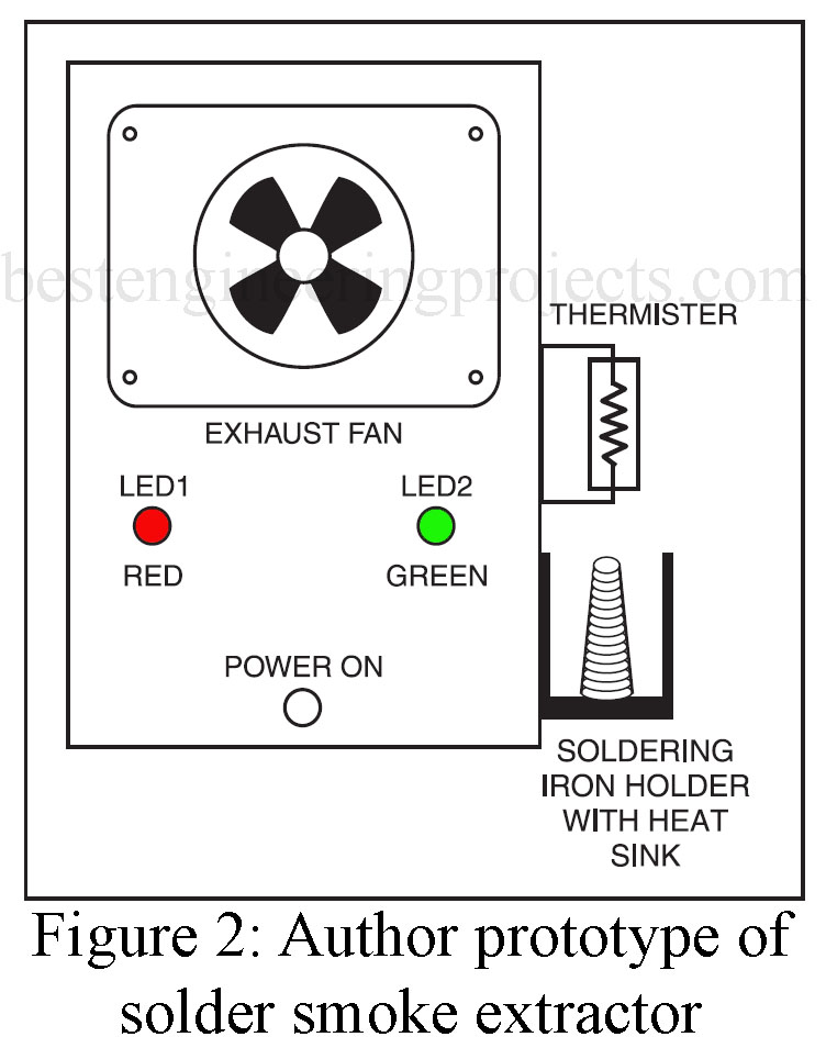
Calibration
Connect all the components as shown in the circuit diagram. Place the thermistor near to heat sink and insulate the leads of the thermistor. Fix the fan so that it pulls all the smoke. Adjust the VR1 until LED2 becomes OFF. Put the assembled circuit in a metal case and make the solder stand over the heat sink as shown in the prototype.