It was determined that an increase in intelligence amplitude resulted in an AM signal with larger maximums and smaller minimums. It is helpful to have a mathematical relationship between the relative amplitude of the carrier and intelligence signals. The percentage modulation provides this, and it is a measure of the extent to which a carrier voltage is varied by intelligence. The percentage modulation is also referred to as modulation index or modulation factor, and they are symbolized by m.
Figure 1 illustrates the two most common methods for determining percentage modulation. Notice that when the intelligence signal is zero, the carrier is unmodulated and has a peak amplitude labeled as EC. When the intelligence reaches its first peak value (point w), the AM signal reaches a peak value labeled Ei (the increase from EC).
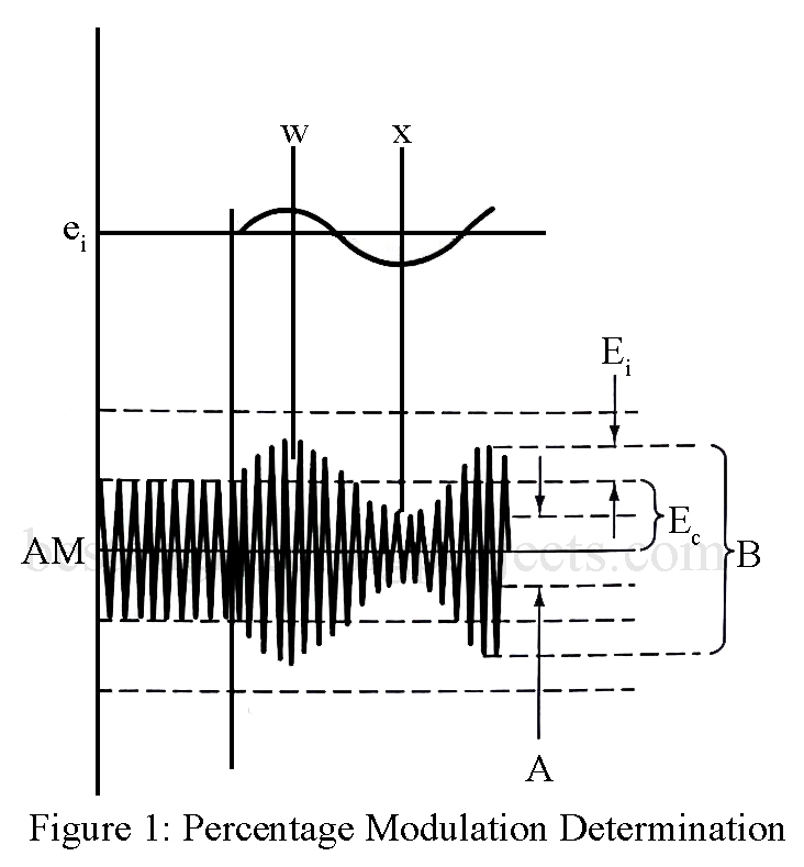
Percentage modulation is then given as
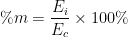
or expressed simply by a ratio:

The same result can be obtained by utilizing the maximum peak-to-peak value of the AM waveform (point w), which is shown as B, and the minimum peak-to-peak value (point x), which is A in the following equation:

This method is usually more convenient in graphical (oscilloscope) solutions.
Overmodulation
If the AM waveform’s minimum value A falls to zero as a result of an increase in the intelligence amplitude, the percentage modulation becomes

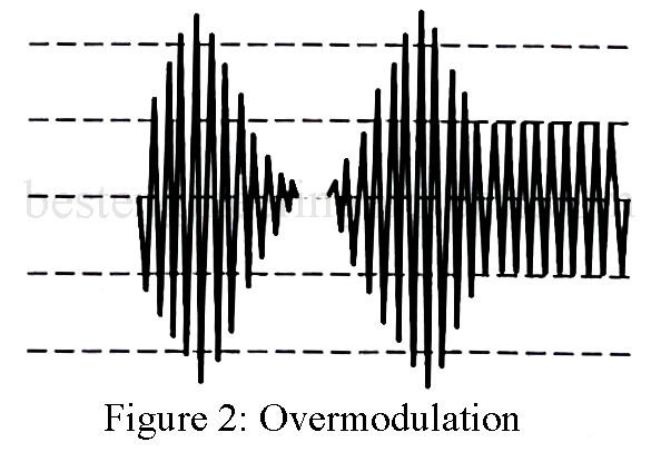
This is the maximum possible degree of modulation. In this situation, the carrier is being varied between zero and double its unmodulated value. Any further increase in the intelligence amplitude will cause a condition known as overmodulation to occur. If this does occur, the modulated carrier will go to more than double its unmodulated value but will fall to zero for an interval of time, as shown in Fig. 2. This “gap” produces distortion termed sideband splatter, which results in the transmission of frequencies outside a station’s normal allocated range. This is an unacceptable condition as it causes severe interference to other stations and causes a loud splattering sound to be heard at the receiver.
EXAMPLE 1: Determine the %m for the following conditions for an unmodulated carrier of 80 V peak-to-peak (p-p).
| MAXIMUM P-P CARRIER (V) | MINIMUM P-P CARRIER (V) | |
| (a) | 100 | 60 |
| (b) | 125 | 35 |
| (c) | 160 | 0 |
| (d) | 180 | 0 |
| (e) | 135 | 35 |
Solution
(a)

(b) 
(c) 
(d) This is a case of overmodulation since the modulated carrier reaches a value more than twice its unmodulated value.
(e) The increase is greater than the decrease in the carrier’s amplitude. This is a distorted AM wave.