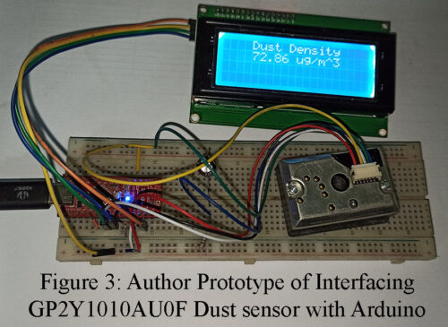
In this article, you will see how to interface GP2Y1010AU0F Dust Sensor with Arduino. GP2Y1010AU0F is an optical dust sensor that can detect very fine particles such as smoke, environmental dust, etc. It is designed for application in commercial air purifiers. However, it is also used in air conditioners and portable air quality monitoring systems. This sensor can detect dust particles up to the size of 0.5 µm. Features of Dust Sensor GP2Y1010AU0F Can easily differentiate smoke and house dust Consumes less current: 20mA max Sense dust particles in less…
Read MoreCircuit of AM Generation
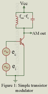
Amplitude modulation is generated by combining carrier and intelligence frequencies through a nonlinear device. Diodes have nonlinear areas, but they are not often used because, being passive devices, they offer no gain. Transistors offer nonlinear operation (if properly biased) and provide amplification, thus making them ideal for this application. Figure 2 shows an input/output relationship for a typical bipolar junction transistor (BJT). Notice that at both low and high values of current, nonlinear areas exist. Between these two extremes is the linear area that should be used for normal amplification.…
Read MoreCalling Bell Circuit Diagram
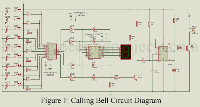
In this article, we are satisfying the curiosity of electronics hobbyists, you and I alike by making a calling bell circuit diagram. The project can be set up in different rooms of an office or hospital and the attendant or office boy waiting place or nursing station. When a call is made from any of the rooms the attendant can be notified through the bell and he/she can verify the room from which the call is made by looking at the display showing the room number. Thus this project allows…
Read MoreImportance of High Percentage Modulation
What is the Importance of High Percentage Modulation? It is important to use as high a percentage modulation as possible while ensuring that overmodulation does not occur. The sidebands contain the information and have maximum power at 100% modulation. For example, if 50% modulation were used, the sideband amplitudes are ¼ the carrier amplitude, and since power is proportional to E2, we have (¼)2, or 1/16 the carrier power. Thus, total sideband power is now 1/16 x 1 kW x 2, or 125 W. The actual transmitted intelligence is thus…
Read MoreMicro SD Card Module and Arduino Interface
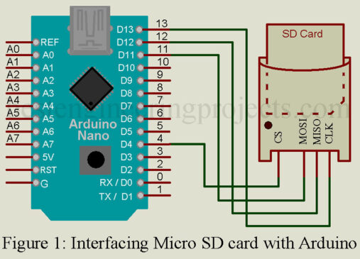
The majority of Microcontroller Units (MCU) include a limited amount of storage space that is adequate to hold your code or software. The Arduino Mega (ATmega2560) has 8 KB of bootloader space, 256 KB of flash memory for code storage, 8 KB of SRAM, and 4 KB of EEPROM (which can be read and written with the EEPROM library). The issue now is what to do if you need to store data for applications like data loggers, data visualization, etc., but the microcontroller unit memory is too small to be…
Read MoreAnalysis of Amplitude Modulation
Analysis of Amplitude Modulation The equation for the amplitude of an AM waveform can be written as the carrier peak amplitude, EC, plus the intelligence signal, ei. Thus, the amplitude E is E = EC + ei but , so that From the above Equation, Ei = mEC, so that The instantaneous value of the AM wave is the amplitude term E just developed times . Thus, Notice that the AM wave (e) is the result of the product of two sine waves. This can be expanded with the help…
Read MorePercentage Modulation | Overmodulation
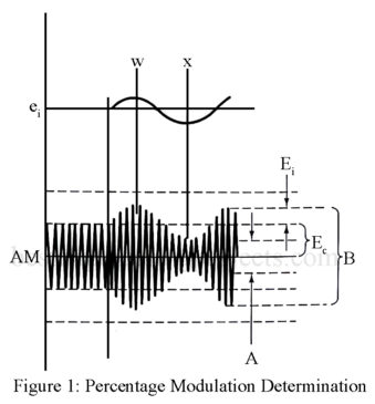
It was determined that an increase in intelligence amplitude resulted in an AM signal with larger maximums and smaller minimums. It is helpful to have a mathematical relationship between the relative amplitude of the carrier and intelligence signals. The percentage modulation provides this, and it is a measure of the extent to which a carrier voltage is varied by intelligence. The percentage modulation is also referred to as modulation index or modulation factor, and they are symbolized by m. Figure 1 illustrates the two most common methods for determining percentage…
Read MoreAutomatic Solder Smoke Extractor
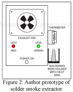
Automatic Solder Smoke Extractor: Soldering is the process of joining electric/electronic components together. It is a very basic and most used process in the field of electronics because it is used to establish a secure connection between PCB and the components. Multiple types of solder wire are available at the market varying in dimensions and quality. Although there are multiple types of solder wires almost all of them are made from Lead and tin. Only the heated iron melts the wire so it is a must to let the iron…
Read MoreThe Importance of Maintaining Elevators in Residential Units
Although few people like to see the skyline of major cities blocked by the number of high-rise buildings, there is no way around it. There is only so much land upon which to build and as the population grows, the only solution is to build up, not out. With that in mind, you can imagine just how important elevators are, especially in residential units. With a condo that is 20+ stories high and apartments with an equal number of floors if not greater, then elevators are beyond an amenity. They…
Read MoreArduino Countdown Timer using P10 Display
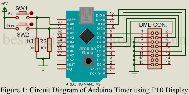
In this article, we make an Arduino Countdown Timer using P10 Display. The counting is done by Arduino and then displayed in the P10 LED module. This project might come in handy for time-keeping purposes during physical games. The details about pin configuration, display specifications, and hardware interfacing between Arduino Nano and P10 are referenced from the “Interfacing P10 single color LED Display with Arduino Nano” article. In this article you will learn two things: How to display a countdown of 3 minutes in P10. How to include a Reset…
Read More